Yaskawa iQpump Programming Manual User Manual
Page 49
YASKAWA TM.iQp.02 iQpump Drive Programming Manual
49
Function: Multi-step SP1 (Setting: 3)
Function: Multi-step SP2 (Setting: 4)
The iQpump drive can be programmed to step through four preset setpoints and a jog reference. It is also possible to mix in the analog
inputs as setpoint references that can be chosen in place of the first and second preset setpoint references. The selection of which preset
setpoint will be the active setpoint is determined by the status of the digital inputs set for Multi-step SP1 (H1-0x = 3) and Multi-step SP2
(H1-0x = 4). Changing the active setpoint via the Multi-step Setpoint References can be done while the iQpump drive is running.
The following table details which reference is active based on the status of the Multi-step SP1 and Multi-step SP2 inputs:
Table 10 Digital Input Functions
The determination of whether the Preset Reference 1 will be the Setpoint Reference 1 (d1-01 or the analog input A1) is determined by the
status of b1-01. If b1-01 = “1: Terminals,” the value of the input to A1 will determine the commanded setpoint when Preset Reference 1
is selected. If b1-01
≠1, the setting of d1-01 will determine the commanded setpoint when Preset Reference 1 is selected.
The determination of Preset Reference 2 is made much the same way as Preset Reference 1 except that the setting of parameter H3-09
decides whether the analog input A2 or d1-02 is Preset Setpoint 2. If H3-09 = “2: Aux Reference,” the value of the input to A2 will
determine the commanded Aux Reference when Preset Reference 2 is selected. If H3-09 = 2, the setting of d1-02 will determine the
commanded setpoint when Preset Reference 2 is selected.
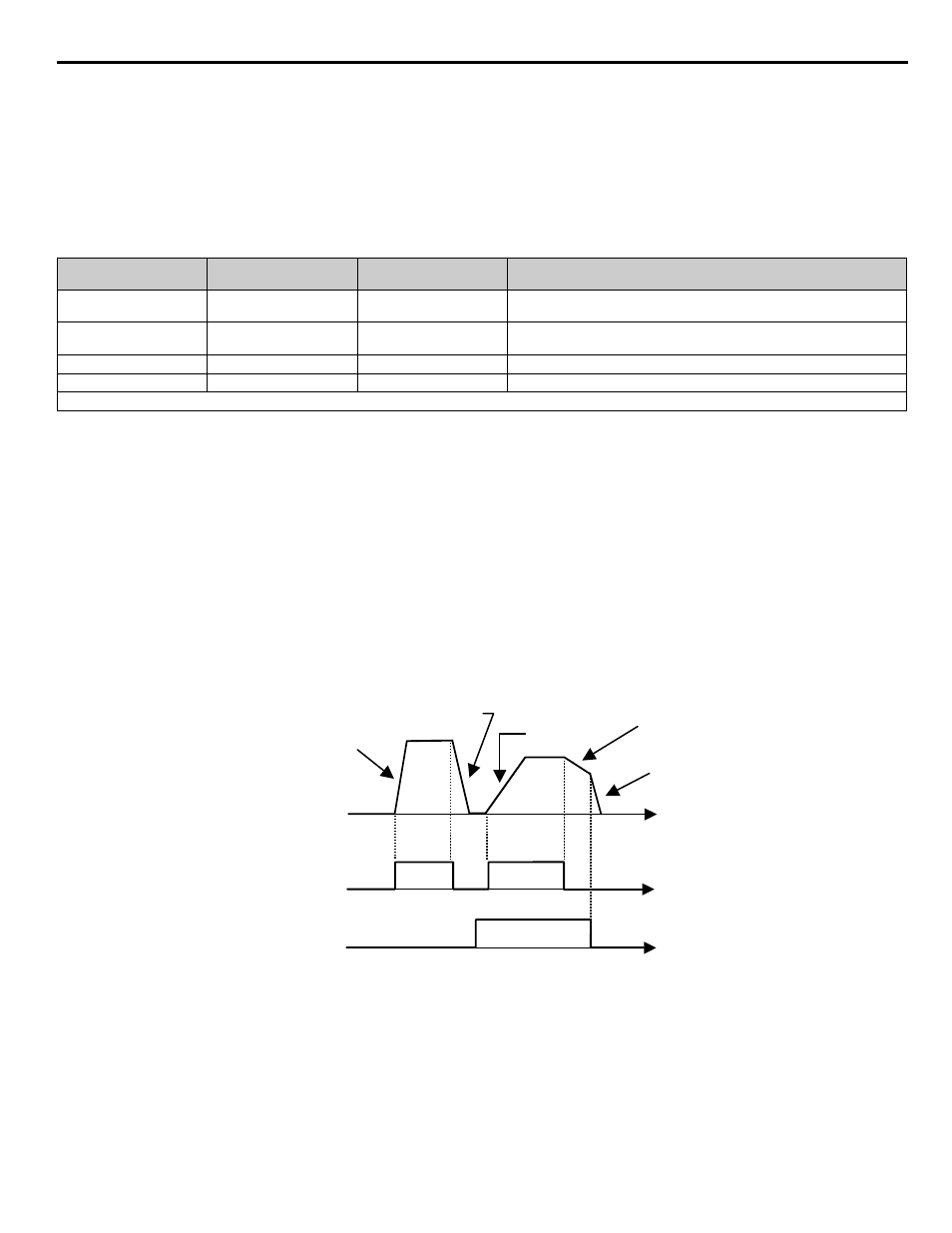
Function: Multi-Acc/Dec 1 (Setting: 7)
When a digital input configured as Multi-Acc/Dec 1 (H1-0x = 7) is OPEN the first set of acceleration/deceleration times (C1-01 and C1-
02) are active.
When a digital input configured as Multi-Acc/Dec 1 (H1-0x = 7) is CLOSED the second set of acceleration/deceleration times (C1-03
and C1-04) are active.
Figure 1.34
Figure 34 Multi-Accel/Dec Timing Diagram
Preset Reference
Terminal Programmed
as Multi-step SP1
Terminal Programmed
as Multi-step SP2
Details
1
OFF
OFF
Setpoint Reference 1 (d1-01) or analog input A1#
(determined by b1-01)
2
ON
OFF
Setpoint Reference 2 (d1-02) or analog input A2#
(determined by H3-09)
3
OFF
ON
Setpoint Reference 3 (d1-03)
4
ON
ON
Setpoint Reference 4 (d1-04)
#
Shown for H3-13=“0: Main Fref TA1”; A1 and A2 are reversed if H3-13=“1: Main Fref TA2”
(C1-01)
Decel Time 1
(C1-02)
Accel Time 2
(C1-03)
Decel Time 2
(C1-04)
Decel Time 1
(C1-02)
Output
Frequency
FWD (REV)
Run Command
Multi-Acc/Dec 1
Input
t
t
t
Accel Time 1
TIME