Yaskawa iQpump Programming Manual User Manual
Page 171
YASKAWA TM.iQp.02 iQpump Drive Programming Manual
171
Figure 1.132
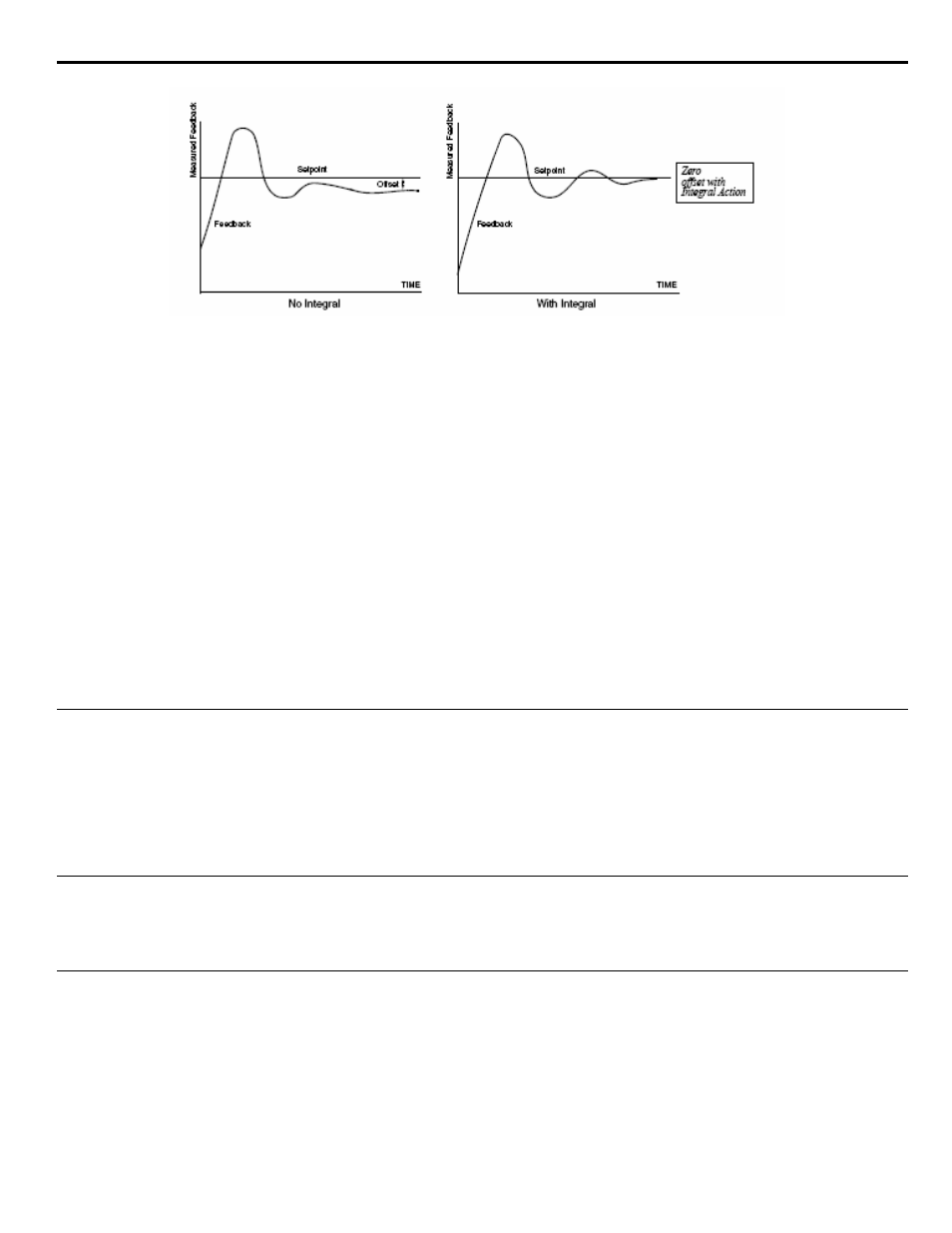
Figure 137 PI Feedback Response Characteristics
The iQpump offers programmable acceleration and deceleration ramps. Each parameter has a setting range of 0.0 to 6000.0 seconds.
Acceleration Time: This is the time it takes to accelerate from 0 Hz to Maximum Output Frequency defined by parameter E1-04.
Deceleration Time: This is the time it takes to decelerate from Maximum Output Frequency defined by parameter E1-04 to 0 Hz.
Example: C1-01 Acceleration Time 1 programmed for 30 seconds, E1-04 Maximum Output Frequency set to 60 Hz. It will take the
iQpump Controller 20 seconds to accelerate from 0 to 40 Hz (40 Hz ÷ 60 Hz x 30 sec = 20 sec).
Example: C1-02 Deceleration Time 1 programmed for 50 seconds, E1-04 Maximum Output Frequency set to 60 Hz. It will take the
iQpump Controller 10 seconds to decelerate from 60 to 30 Hz (30 Hz ÷ 60 Hz x 50 sec = 25 sec).
■
Factory Default Settings for C1-01 Acceleration Time and C1-02 Deceleration Time is
25.0 Seconds
Thrust Bearing Operation (see
“P4-04 Thrust Bearing Acceleration Time: on page 156
) uses a separate acceleration time defined by
parameter P4-04. Once Thrust frequency is reached, the iQpump drive returns to its normal acceleration time set by C1-01.
Pre-Charge mode uses C1-01 as its acceleration time.
Hand Mode Operation uses C1-01 and C1-02 for acceleration and deceleration time.
Auto Mode can use acceleration time C1-05 and deceleration time C1-06, depending on parameter P3-12 setting (see section.
Delta Setpoint Feedback Acc/Dec Changeover on page 155
.)
◆
System Response During Normal Automatic Operation (P3-12)
Acceleration and Deceleration times can automatically be adjusted during Automatic Setpoint regulation to improve system stability.
■
Enable Alternate Acceleration / Deceleration Ramps based on Set-Point and Feedback Level
To enabled the alternate acceleration and deceleration time, parameter P3-12 has to be programmed to a value greater than 0.
Please refer to section
P3-12 Delta Setpoint Feedback Acc/Dec Changeover on page 155
for a detailed explanation.
◆
Friction Compensation for Single Pump Systems (P3-13, P3-14)
Please refer to section
P3-13 Friction Compensation Start Frequency on page 156
and
P3-14 Maximum Friction Increase at
for a detailed explanation.
◆
Friction Compensation for Multi-Pump Systems (P3-07, P3-08)
P3-07 Multi Pump Setpoint Increase on page 151
P3-08 Multi Pump Setpoint Decrease on page 152
for a
detailed explanation.