Yaskawa iQpump Programming Manual User Manual
Page 188

188
YASKAWA
TM.iQp.02 iQpump Drive Programming Manual
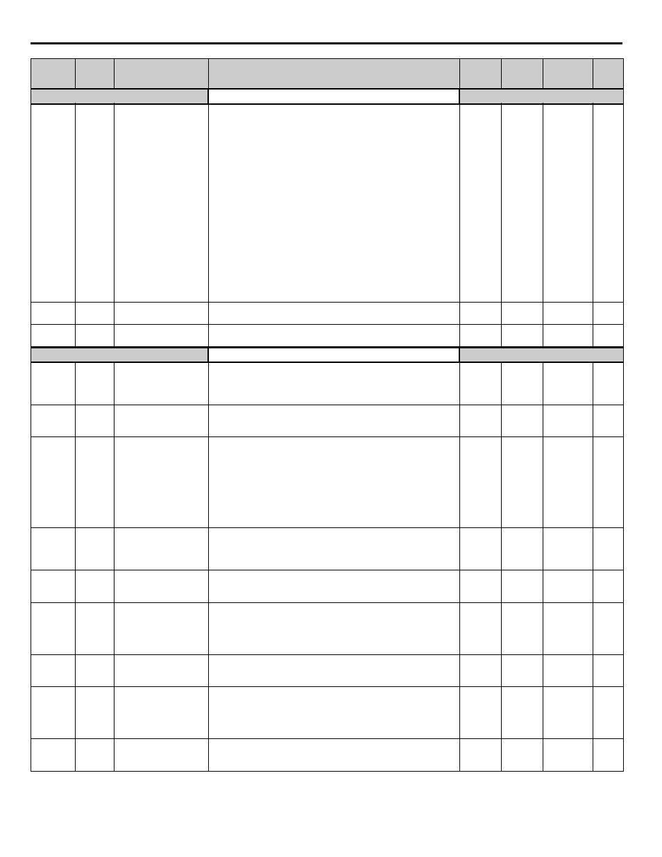
Torque Detection
L6-01
04A1H
Torque Detection
Selection 1
Load Detection
Determines the Drive's response to an overtorque / undertorque
condition. Overtorque and Undertorque are determined by the settings
in parameters L6-02 and L6-03.
0: Disabled
1: OL@SpdAgree - Alm (Overtorque Detection only active during
Speed Agree and Operation continues after detection)
2: OL At RUN - Alm (Overtorque Detection is always active and
operation continues after detection)
3: OL@SpdAgree - Flt (Overtorque Detection only active during
Speed Agree and Drive output will shut down on an OL3 fault.)
4: OL At RUN - Flt (Overtorque Detection is always active and Drive
output will shut down on an OL3 fault.)
5: LL@SpdAgree - Alm (Undertorque Detection is only active during
Speed Agree and operation continues after detection.)
6: LL at RUN - Alm (Undertorque Detection is always active and
operation continues after detection.)
7: LL @ SpdAgree - Flt (Undertorque Detection only active during
Speed Agree and Drive output will shut down on an OL3 fault.)
8: LL At RUN - Flt (Undertorque Detection is always active and Drive
output will shut down on an OL3 fault.)
0 to 8
0
Programming
L6-02
04A2H
Torque Detection Level 1
Load Det Lvl
Sets the overtorque/undertorque detection level as a percentage of
Drive rated current.
0 to 300
15%
Programming
L6-03
04A3H
Torque Detection Time 1
Loss Det Time
Sets the length of time an overtorque / undertorque condition must
exist before being recognized by the Drive. OL3 is then displayed.
0.0 to 10.0 10.0 sec Programming
Hdwe Protection
L8-01
04ADH
Internal Dynamic
Braking Resistor
Protection Selection
DB Resistor Prot
0: Not Provided
1: Provided
0 or 1
0
Programming
L8-02
04AEH
Overheat Pre-Alarm
Level
OH Pre-Alarm Lvl
When the cooling fin temperature exceeds the value set in this
parameter, an overheat pre-alarm (OH) will occur.
50 to 130
95°C
Programming
L8-03
04AFH
Overheat Pre-Alarm
Operation Selection
OH Pre-Alarm Sel
Drive Operation upon OH Pre Alarm Detection.
0: Ramp to Stop (Decel Time C1-02).
1: Coast to Stop
2: Fast-Stop (Decel Time = C1-09).
3: Alarm Only
*0 to 2 is recognized as fault detection, and 3 is recognized as alarm.
(For the fault detection, the fault contact operates.)
4: OH Alarm & Reduce (Continue operation and reduce output
frequency by L8-19)
0 to 4
4
Programming
L8-05
<0033>
04B1H
Input Phase Loss
Protection Selection
Ph Loss In Sel
Selects the detection of input current phase loss, power supply voltage
imbalance, or main circuit electrostatic capacitor deterioration.
0: Disabled
1: Enabled
0 to 1
1
Programming
L8-06
04B2H
Input Phase Loss
Detection Level
Ph Loss In Lvl
Monitors the DC Bus current ripple and activates when one of the input
phases is lost (PF).
0.0 to 25.0
0.5%
Programming
L8-07
<0033>
04B3H
Output Phase Loss
Protection Selection
Ph Loss Out Sel
Selects the detection of output current open-phase.
When applied motor capacity is too small for Drive capacity, output
phase loss may be detected inadvertently. In this case, set to 0.
0: Disabled
1: Enabled
0 to 1
1
Programming
L8-09
04B5H
Output Ground Fault
Detection Selection
Ground Fault Sel
Enables and disables Drive output ground fault detection.
0: Disabled
1: Enabled
0 or 1
1
Programming
L8-10
04B6H
Heatsink Cooling Fan
Operation Selection
Fan On/Off Sel
Controls the Heatsink Cooling Fan Operation.
0: Fan On-Run Mode (Fan will operate only when Drive is running and
for L8-11 seconds after RUN is removed).
1: Fan Always On (Cooling fan operates whenever Drive is powered
up.)
0 or 1
0
Programming
L8-11
<0032>
04B7H
Heatsink Cooling Fan
Operation Delay Time
Fan Delay Time
When L8-10=0 this parameter sets a delay time for Cooling Fan de-
energization after the run command is removed or baseblock enabled.
0 to 300
300 sec Programming
Parameter
No.
Modbus
Address
Parameter Name
Digital Operator
Display
Description
Setting
Range
Factory
Setting
Menu
Location
Page
No.