Yaskawa iQpump Programming Manual User Manual
Page 61
YASKAWA TM.iQp.02 iQpump Drive Programming Manual
61
Function: Low Water Level (Setting: 85)
A digital input can be configured to indicate a Low Water Level Fault (H1-0x = 85). The Low Water Level input can be configured as a
normally open or normally closed contact by programming the Low Level Input (P1-15). When P1-15 = 0, a Low Water Level Fault will
occur when the contact is closed. An open contact will indicate the drive is operating under normal operating conditions.
When P1-15 = 1, a Low Water Level Fault will occur when the contact is open. A closed contact will indicate the drive is operating under
normal operating conditions.
If the Pre-Charge function is activated, the Low Water Level will not cause a Low Water Level Fault. The Low Water Level will only
indicate that the Pre-Charge function has been completed.
If the drive is operating under normal operating condition and a Low Water Level occurs, the drive will indicate a Low Water Level Fault
(LFB/LW) on the digital operator.
To reset the Low Water Level Fault would require the removal of the run command, initiate a fault reset, and restart the drive using the
Pre-Charge function.
Note: Low Water Level Fault is only active in the Auto Mode and inactive during the Pre-Charge function.
Figure 1.48
Figure 48 Lower Water Fault on Operator
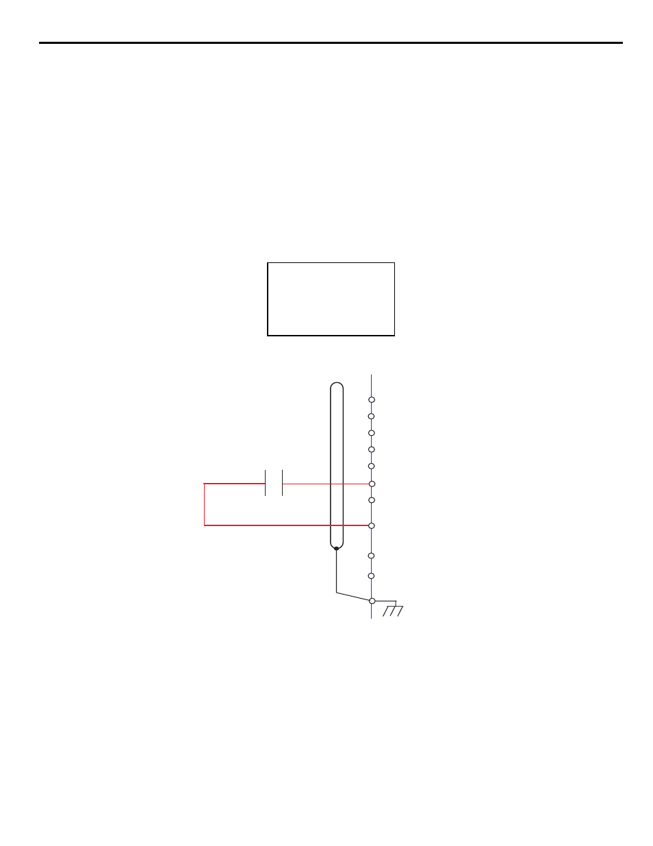
Figure 1.49
Figure 49 Wiring Diagram
Function: Fixed Speed Auto (Setting: 86)
A digital input can be configured to enable the Fixed Speed Auto (H1-0x = 86) when operating in the Auto Mode. A contact closure into
the multi-function input will enable the Fixed Speed Auto function.
The Fixed Speed Auto will cause the drive to run at the iQpump drive Multi/Maximum Level (P3-02) and disable the PI Control, Sleep
Mode and Lead/Lag operation.
When the digital input is open, the Fixed Speed Auto is disabled.
Note: Pre-Charge and Thrust Bearing functions have a higher priority than Fixed Speed Auto.
-DRIVE-
Low FB / Water
LFB/
U2-04 =
U2-05 =
0.00 Hz
0.00 A
External Switch or
Relay Contact
Low Water Level
H1-04 = 85
(Low Water Level)
S1
S2
S3 (H1-01)
S4 (H1-02)
S5 (H1-03)
S6 (H1-04)
S7 (H1-05)
SC
SP 24 VDC +/- 20%, 8 mA
E (G)
SN