Yaskawa iQpump Programming Manual User Manual
Page 57
YASKAWA TM.iQp.02 iQpump Drive Programming Manual
57
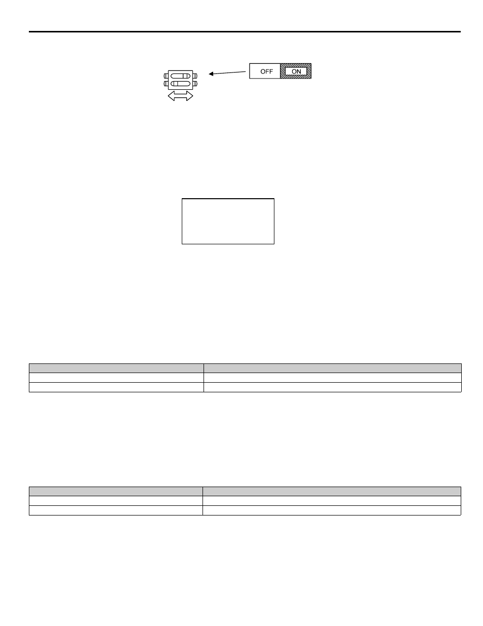
4. Turn On the terminating resistance (Move Switch 1 of Dip Switch 1 to the ON position).
Figure 1.41
Figure 41 DIP Switch Setting for Terminating Resistor
5. Turn on power to the Drive.
After step 5 above the iQpump drive will either display “Pass” if everything is okay or a CE alarm will be displayed. If the CE alarm
occurs, the fault output contact will energize.
Function: Drive Enable (Setting: 6A)
A digital input configured as an iQpump drive Enable input (H1-0x = 6A) will prevent the iQpump drive from executing a Run command
until it is closed. When the iQpump drive Enable input is open the digital operator will display:
If a Run command is closed prior to the iQpump drive Enable input being closed the iQpump drive will not run until the Run command is
cycled.
If the iQpump drive Enable input is opened while the iQpump drive is running, the iQpump drive will stop, using the method set by
parameter b1-03.
Function: Com/Inv Sel (Setting: 6B)
Function: Com/Inv Sel 2 (Setting: 6C)
The Com/Inv Selection function allows the user to switch the origin of the Run and speed command between the Drive’s terminals and
the RS-485/422 port (and the embedded communication protocols) on the removable terminal board. When a digital input is programmed
for the Com/Inv Selection function (H1-0x = 6B) that input will function as follows:
Table 14 6B, COM/INV SEL
To switch the command source between the serial communication port and the control circuit terminals be sure to program the following
parameters:
• Set b1-01 (Auto Setpoint Reference Selection) to 1 (Terminals).
• Set b1-02 (Run Command Selection) to 1 (Terminals).
• Set H1-0x (Input Terminal Function Selection) to 6B or 6C.
The Com/Inv Sel 2 function will operate the same way except the logic is reversed. When a digital input is programmed for the Com/Inv
Selection function (H1-0x = 6C) that input will function as follows:
Table 15 6C, COM/INV SEL 2
Important: Switching the Reference and Run sources can only be done while the iQpump drive is stopped.
Option/Inv Function Input Status
Run and Speed Command Source
OPEN
From the control circuit and analog input terminals (follows b1-01)
CLOSED
From Serial Comm port (R+,R-,S+, and S-) (embedded protocols)
Option/Inv Function Input Status
Run and Speed Command Source
OPEN
From Serial Comm port (R+, R-, S+, and S-) (embedded protocols)
CLOSED
From the control circuit and analog input terminals (follows b1-01)
S1
O
F
F
1
Terminating
resistance
DIP Switch S1 located on
removable terminal board.
2
1
-DRIVE-
DNE
Drive Not Enable