Yaskawa iQpump Programming Manual User Manual
Page 27
YASKAWA TM.iQp.02 iQpump Drive Programming Manual
27
■
b5-09 PI Output Level Selection
Normally, the output of the PI function causes an increase in motor speed whenever the measured feedback is below the setpoint. This is
referred to as direct acting response. However, if b5-09 = “1: Reverse Output,” the output of the PI function causes the motor to slow
down when the feedback is below the setpoint. This is referred to as reverse acting response.
■
b5-10 PI Output Gain Setting
Setting Range:
0.0 to 25.0
Factory Default: 1.0
Applies a multiplier to the output of the PI function. Using the gain can be helpful when the PI function is used to trim the Speed
Command. Increasing b5-10 causes the PI function to have a greater regulating affect on the speed command.
■
b5-12 PI Feedback Reference Missing Detection Selection
Loss of feedback can cause problems to a PI application. The iQpump drive can be programmed to turn on a digital output whenever a
loss of feedback occurs. Feedback Loss Detection (FBL) is turned on by b5-12. When b5-12 = “1: Alarm,” the iQpump drive
acknowledges the loss of feedback without stopping or turning on the fault output (MA-MB). If b5-12 = “2: Fault,” the iQpump drive
coasts to a stop and turns on the fault output if the feedback is determined to be lost.
The Feedback Loss Detection can be disabled during the following conditions:
• Pre-Charge Level (P4-01) is set to 0.
• Thrust Bearing acceleration or deceleration.
Note: A Feedback Loss Detection (FBL) will occur when the Thrust Bearing function is enabled and a run command given, P1
Feedback Loss Detection Time (b5-14) is set to 0, and P1 Feedback is below Feedback Loss Detection Level (b5-13).
■
b5-13 PI Feedback Loss Detection Level
Setting Range:
0 to 100%
Factory Default: 0%
■
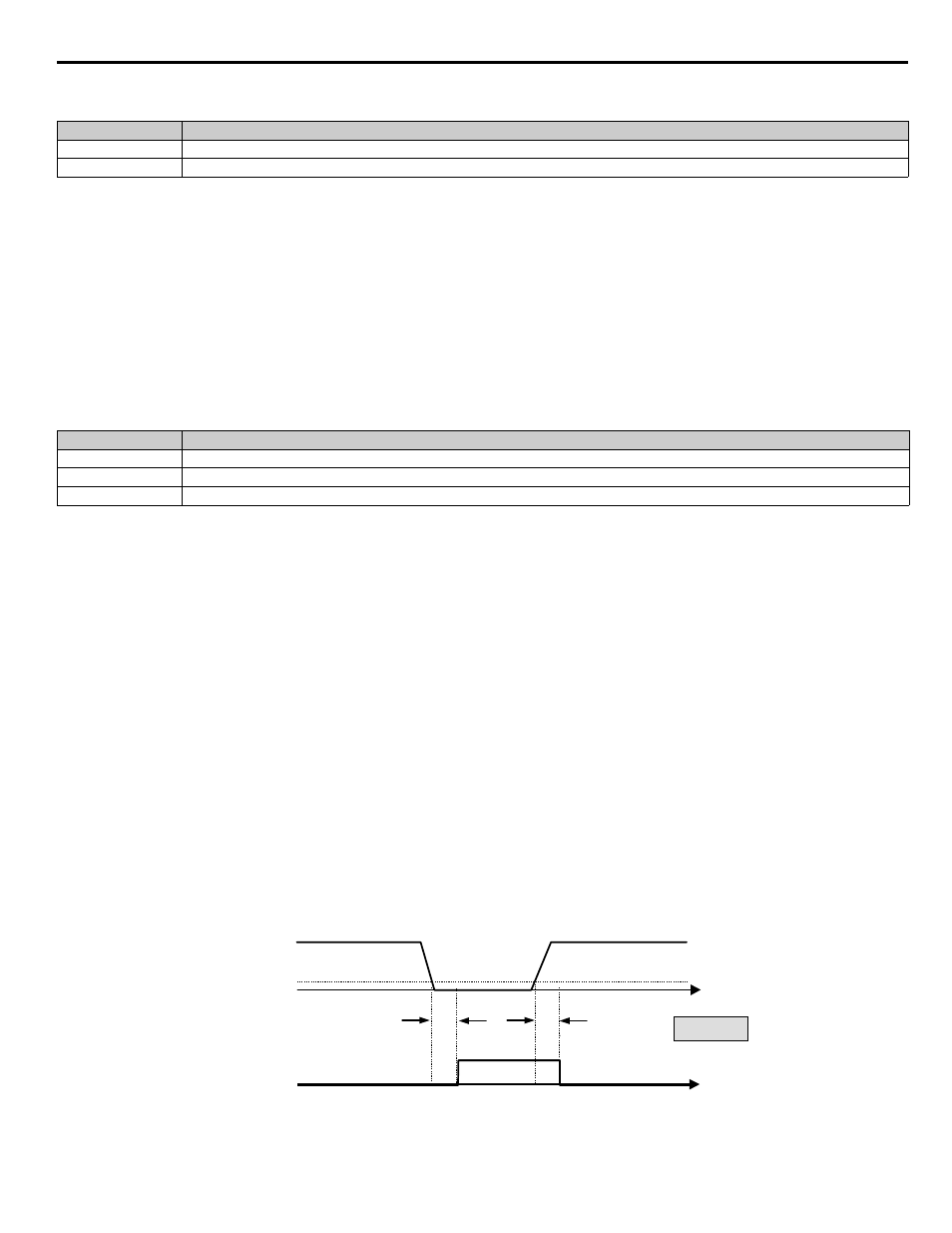
b5-14 PI Feedback Loss Detection Time
Setting Range:
0.0 to 25.0 sec
Factory Default: 1.0 sec
The iQpump drive interprets feedback loss whenever the feedback signal drops below the value of b5-13 and stays below that level for at
least the time set into b5-14. See
for timing details.
Figure 1.23
Figure 23 Loss of PI Feedback Feature
Setting
Description
0
Normal Output (direct acting) (factory default)
1
Reverse Output (reverse acting)
Setting
Description
0
Disabled (factory default)
1
Alarm
2
Fault
Measured
Feedback
T
t
Feedback
Loss Output
T
b5-13
T = b5-14
Feedback
Loss Digital Output
ON (CLOSED)
OFF (OPEN)
TIME