Figure 117, For the stagin – Yaskawa iQpump Programming Manual User Manual
Page 147
YASKAWA TM.iQp.02 iQpump Drive Programming Manual
147
Figure 1.112
Figure 117
The pump system can be allowed to stabilize by programming a time into the Multiplex Stabilization Time (P3-11). The Multiplex
Stabilization Time (P3-11) becomes active after an auxiliary pump is staged or de-staged.
Note: The pump protection function is disabled during auxiliary pump staging and de-staging.
The No-Flow and Sleep functions are only active when the lead pump controlled by the drive is the only pump operating the pump
system.
P3-01 = 2: Output Frequency + Feedback Level
The “output frequency + feedback level” control method monitors the drive’s output frequency and the difference between the system’s
setpoint and feedback level to determine if the auxiliary pumps need to be staged (turned ON) to maintain the programmed system’s
setpoint. The output frequency and the difference between the system’s setpoint and feedback level also determine when the auxiliary
pumps are to be de-staged (turned OFF). Refer to
and
for the staging and de-staging of the auxiliary pumps using
the “output frequency + feedback level” control method.
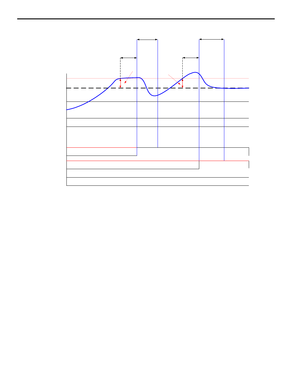
Auxiliary Pump Staging (ON)
The staging of auxiliary pump 2 occurs when the output frequency remains above the iQpump drive Multi/Maximum Level (P3-02) and
the difference between the system’s setpoint and the feedback level exceeds the value programmed in the Add Pump Delta Level (P3-03)
for the time programmed in Add Pump Delay Time (P3-04).
The staging of auxiliary pump 3 occurs when the auxiliary pump 2 is staged and when the output frequency remains above the iQpump
drive Multi/Maximum Level (P3-02) and the difference between the system’s setpoint and feedback level exceeds the value programmed
in the Add Pump Delta Level (P3-03) for the time programmed in Add Pump Delay Time (P3-04). Refer to
for the staging of
the auxiliary pumps using the “output frequency + feedback level” control method.
TIME
Feedback
Auto Mode Run
Multi-function
Output #40
0%
OFF Mode
Shutdown Pump
Delta Level P3-05
Start System, Incoming Run Command
Start System
System
Set-Point
Multi-function
Output #41
PUMP 1 + 2 + 3 RUNNING
Multiplex Stabilize Time
P3-11
Multiplex Stabilize Time
P3-11
Shutdown Pump Delta Level
P3-05
Shutdown Pump Delay Time
P3-06
Shutdown Pump Delay Time
P3-06
REMOVE PUMP 3
Open Contact
REMOVE PUMP 2
Open Contact