Yaskawa iQpump Programming Manual User Manual
Page 51
YASKAWA TM.iQp.02 iQpump Drive Programming Manual
51
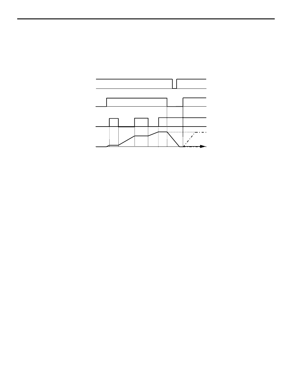
Function: Acc/Dec RampHold (Setting: A)
The Acc/Dec RampHold function will clamp (“hold”) the speed of the output frequency whenever a digital input that has been
programmed for it (H1-0x = A) is closed. All acceleration or deceleration will stop and the iQpump drive will hold the current speed.
Once the input is opened, acceleration or deceleration continues.
The Acc/Dec RampHold function is affected by parameter d4-01. If d4-01 = “1: Enabled” and the Acc/Dec RampHold functions are both
being used, whenever the RampHold input is closed the output frequency is memorized. When interrupted power is returned and a Run
command is input, the Speed Command will be the last output frequency memorized by the Acc/DecRampHold function, if the Acc/Dec
RampHold input is still closed.
Figure 1.36
Figure 36 Accel/Dec RampHold Function Timing Diagram
Function: Term A2 Enable (Setting: C)
Any digital input configured as Term A2 Enable (H1-0x = C) when open will cause the input to analog input A2 to be ignored.
If analog input A2 is configured as the Main Reference (H3-13 = “1: Main Fref TA1”), then the Term A2 Enable input will have no
effect.
Function: Term Not Used (Setting: F)
Any digital input programmed as Term Not Used (H1-0x = F) will have no function assigned to it and it’s OPEN/CLOSED state will not
matter to the Drive’s operation.
Function: MOP Increase (Setting: 10)
Function: MOP Decrease (Setting: 11)
Using two digital inputs, the iQpump drive can operate with the same type of functionality as a motor operated potentiometer (MOP).
One digital input can be programmed as an MOP Increase input (H1-0x = 10) and another digital input can be programmed as an MOP
Decrease input (H1-0x = 11). This MOP functionality is also commonly referred to as Floating Point Control, Incremental Control or UP
and DOWN Control since closing the MOP Increase input will cause the speed command to increase and closing the MOP Decrease
input will cause the speed command to decrease.
If both the MOP Increase and the MOP Decrease are closed or open simultaneously, the speed will command will not change. The speed
command will change at the active acceleration or deceleration rate.
MOP Increase cannot be programmed without also programming the MOP Decrease (or vice versa) else an OPE03 fault will occur.
Setting the MOP Increase/Decrease function while the Acc/Dec RampHold function is programmed into other digital inputs will also
cause an OPE03 fault.
Once the MOP function is programmed the preset speeds are disabled and the analog speed command input becomes a potential
frequency reference lower limit. The lower limit of the MOP function is the greater of the analog speed command and the programmed
frequency reference lower limit (d2-03). Once a Run command is issued the iQpump drive will accelerate immediately to the lower limit.
The upper limit will be the Frequency Reference Upper Limit (d2-01), if used, otherwise the Maximum Frequency (E1-04).
The status of the d4-01 parameter (MOP Reference Memory) will affect the performance of the iQpump drive after power is cycled to the
iQpump drive and a fresh Run command is issued. If d4-01 = “0: Disabled,” the Run command will cause the iQpump drive to ramp to
the frequency reference lower limit. However, if d4-01 = “1: Enabled,” the Run command will cause the iQpump drive to ramp to the last
speed commanded by the MOP function before the Run command was removed and the power cycled. Even if d4-01 = “1: Enabled,” the
previous speed command can be reset to the frequency reference lower limit automatically by closing either the UP or Down input
without having a Run command active.
Run
Command
Hold Input
Output
Frequency
Input
Power
d4-01=1
d4-01=0
ON
ON
ON
OFF
OFF
OFF
TIME
Input Power
Run
Command
Hold Input
Output
Frequency