H3 analog inputs, H3-02 terminal a1 gain setting, H3-03 terminal a1 bias setting – Yaskawa iQpump Programming Manual User Manual
Page 70
70
YASKAWA
TM.iQp.02 iQpump Drive Programming Manual
◆
H3 Analog Inputs
■
H3-02 Terminal A1 Gain Setting
Setting Range:
0.0 to 1000.0%
Factory Default: 100.0%
■
H3-03 Terminal A1 Bias Setting
Setting Range:
-100.0% to +100.0%
Factory Default: 0.0%
In order to have the iQpump drive properly interpret an analog input, it may be necessary to apply a gain and/or a bias to the signal. The
analog inputs have a resolution of 10 bits (1024 steps). Using the factory default settings for the analog input’s gain and bias, the 0-10
Vdc or 4-20 mA signal at the analog input will yield a 0-100% speed command span.
Figure 1.61
Figure 61 Output Frequency as Commanded Via Analog Input
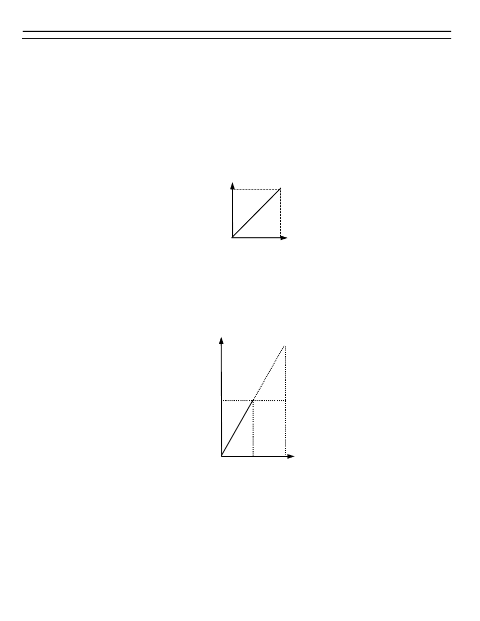
If a different span of analog input signal is desirable, it will be necessary to adjust the gain, the bias, or both to allow the analog input
level to generate the desired frequency command. Adjustment of the gain setting will change the speed command that is equivalent to the
maximum analog input (10 Vdc or 20 mA). If, for instance, the gain is increased to 200%, then 10 Vdc or 20 mA will be equivalent to a
200% speed command and 5 VAC or 12 mA will be equivalent to a 100% Speed Command. Since the iQpump drive output is limited by
the maximum frequency parameter (E1-04), 0-5 Vdc or 4-12 mA will now be equivalent to 0-100% speed command span.
Figure 1.62
Figure 62 Output Frequency as Commanded via Analog Input with Increased Gain Setting
Adjustment of the bias setting will likewise adjust the speed command that is equivalent to the minimum analog input level (0 Vdc or 4
mA). If, for instance, the bias is set to –25%, then 0 Vdc or 4 mA will be equivalent to a –25% speed command. Since the minimum
speed command is 0% an analog input of 2.5 to10 Vdc or 8 to 20 mA will now be equivalent to 0-100% speed command span.
20mA
4mA
0V
10V
Gain = 100%
Bias = 0%
Out
put
F
req
uen
cy
Analog Input Level
Signal
4mA
20mA
0V
10V
Bias = 0%
O
ut
put
Fre
quenc
y
Analog Input Level
Gain =200%
100%
Analog Input Signal
5V
12mA