Modbus self-diagnosis – Yaskawa iQpump Programming Manual User Manual
Page 93
YASKAWA TM.iQp.02 iQpump Drive Programming Manual
93
◆
Modbus Self-Diagnosis
The iQpump drive has a built-in function for self-diagnosing the operations of serial communication interface circuits. The self-diagnosis
function connects the communication parts of the send and receive terminals, receives the data sent by the Drive, and checks if
communication is being performed normally.
Perform the self-diagnosis function using the following procedure.
1. Turn ON the power supply to the Drive, and set parameter H1-05 (Terminal S7 Function Selection) to 67 (Comm Test Mode).
2. Turn OFF the power supply to the Drive.
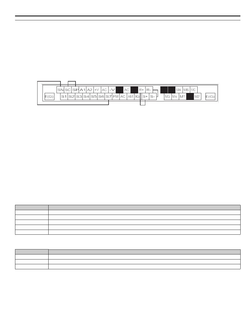
3. Perform wiring according to the following diagram while the power supply is turned OFF.
4. Turn ON the terminating resistance. (Turn ON pin 1 on DIP switch 1.)
5. Turn ON the power supply to the iQpump drive again.
Figure 1.80
Figure 85 Communication Terminal Connection for Self -Diagnosis Function
6. During normal self-diagnostic operation, the Digital Operator displays the frequency reference value. If an error occurs, a CE (Modbus
communication error) alarm will be displayed on the Digital Operator, the fault contact output will be turned ON, and the iQpump
drive operation ready signal will be turned OFF.
■
H5-01 Drive Node Address
In order for a master to be able to communicate with the iQpump drive using serial communications, the iQpump drive must have a
unique node address. The iQpump drive is given a node address if H5-01¼0. The node addresses do not have to be assigned in sequential
order but they must be unique, i.e. no two Drives on the same serial network can be assigned the same address. After setting the iQpump
drive address with the H5-01 parameter, the power to the iQpump drive must be cycled for the addressing to take effect.
Leaving H5-01 = 0 will disable responses to MEMOBUS communications.
■
H5-02 Communications Speed Selection
■
H5-03 Communications Parity Selection
Parameters H5-02 and H5-03 configure the Drives MEMOBUS communications via the RS-485/422 terminals on the removable
terminal block. Configure H5-02 and H5-03 to match the settings of the master controller of the serial network. After changing the H5-02
or H5-03 parameter, the power to the iQpump drive must be cycled for the change to take effect.
If either the speed or parity value is changed via the serial communications, the serial communications will cease to operate until the
iQpump drive power is cycled.
Setting Range:
0 to 20
(Hex)
} MODBUS
0 to FF
} N2
0 to 63
} P1
Factory Default:
1F
1F
1F
Setting
Description
0
1200 Baud
1
2400 Baud
2
4800 Baud (Standard for APOGEE)
3
9600 Baud (
factory default) (Standard for Metasys)
4
19200 Baud
Setting
Description
0
No Parity (
factory default)
1
Even Parity
2
Odd Parity