Governor bias control settings – Basler Electric DGC-2020HD User Manual
Page 125
9469300990 Rev B
115
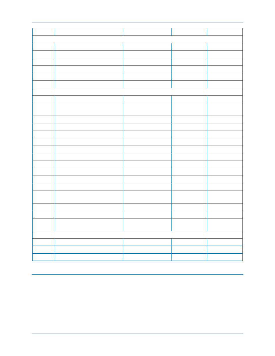
Locator
Setting
Range
Increment
Unit
Voltage Settings
E
Trim Enable
Disable or Enable
n/a
n/a
F
Kp Proportional Gain
0 to 1,000
0.001
n/a
G
Ki Integral Gain
0 to 1,000
0.001
n/a
H
Kd Derivative Gain
0 to 1,000
0.001
n/a
I
Td Derivative Filter Constant
0 to 1
0.001
n/a
J
Kg Loop Gain
0 to 1,000
0.001
n/a
var/PF Settings
K
Control Enable
Disable or Enable
n/a
n/a
L
Control Mode
var Control or PF
Control
n/a
n/a
M
Kp Proportional gain
0 to 1,000
0.001
n/a
N
Ki Integral Gain
0 to 1,000
0.001
n/a
O
Kd Derivative Gain
0 to 1,000
0.001
n/a
P
Td Derivative Filter Constant
0 to 1
0.001
n/a
Q
Kg Loop Gain
0 to 1,000
0.001
n/a
R
Droop Percentage
0 to 10
0.001
%
S
Voltage Droop Gain
0 to 1,000
0.001
n/a
T
Ramp Rate
0 to 100
0.1
% per second
U
Ramp Overshoot Reduction
0 to 100
1
%
V
kvar Setpoint
–100 to +100
0.1
%
W
kvar Setpoint Source
User Setting or Aux
Input 1 to 4
n/a
n/a
X
kvar Analog Max
–100 to +100
0.1
%
Y
kvar Analog Min
–100 to +100
0.1
%
Z
PF Setpoint Source
User Setting or Aux
Input 1 to 4
n/a
n/a
(– Leading / + Lagging) Settings
AA
PF Setpoint
+0.6 to –0.6
0.01
n/a
BB
PF Analog Max
+0.6 to –0.6
0.01
n/a
CC
PF Analog Min
+0.6 to –0.6
0.01
n/a
Governor Bias Control Settings
BESTCOMSPlus Navigation Path: Settings Explorer, Bias Control Settings, Governor Bias Control
Settings
Front Panel Navigation Path: Settings > Bias Control > Gov Bias Control
When the bias control output type is set to contact, the DGC-2020HD adjusts the generator voltage and
frequency by issuing speed correction signals to the generator governor. Correction signals are issued in
the form of DGC-2020HD output contact closures. These correction signals can be either continuous or
proportional. Proportional correction uses control pulses of varying widths and intervals. Initially, long
pulses are issued when the voltage and frequency differences are large. As the correction pulses take
effect and the voltage and frequency differences become smaller, the correction pulse widths are
DGC-2020HD
Bias Control