Retrieving a logic scheme from the dgc-2020hd, Programming bestlogic™plus, Programming bestlogic – Basler Electric DGC-2020HD User Manual
Page 245: Plus, Programming bestlogic ™plus
9469300990 Rev B
235
Retrieving a Logic Scheme from the DGC-2020HD
To retrieve settings from the DGC-2020HD, it must be connected to a computer through a
communications port. Once the necessary connections are made, settings can be downloaded from the
DGC-2020HD by selecting Download Settings and Logic from Device on the Communication pull-down
menu.
Programming BESTlogic
™Plus
Use BESTCOMSPlus to program BESTlogicPlus. Using BESTCOMSPlus is analogous to physically
attaching wire between discrete DGC-2020HD terminals. To program BESTlogicPlus, use the Settings
Explorer within BESTCOMSPlus to open the BESTlogicPlus Programmable Logic tree branch as shown
in Figure 146.
The drag and drop method is used to connect a variable or series of variables to the logic inputs, outputs,
components, and elements. To draw a wire/link from port to port (triangles), click the left mouse button on
a port, pull the wire onto another port, and release the left mouse button. A red port indicates that a
connection to the port is required or missing. A black port indicates that a connection to the port is not
required. Drawing wires/links from input to input or output to output is not allowed. Only one wire/link can
be connected to any one output. If the proximity of the endpoint of the wire/link is not exact, it may attach
to an unintended port.
If an object or element is disabled, it will have a yellow X on it. To enable the element, navigate to the
settings page for that element. A red X indicates that an object or element is not available per the style
number of the DGC-2020HD.
The view of Logic Page 1 through 4, Physical Outputs, Remote Outputs, and LCR Outputs can be
automatically arranged by clicking the right mouse button on the window and selecting Auto-Layout.
The following must be met before BESTCOMSPlus will allow logic to be uploaded to the DGC-2020HD:
•
A minimum of two inputs and a maximum of 32 inputs on any multi-port (AND, OR, NAND, NOR,
XOR, and XNOR) gate.
•
A maximum of 32 logic levels for any particular path. A path being an input block or an output
side of an element block through gates to an output block or an input side of an element block.
This is to include any OR gates on the Physical Output or Remote Output tab/pages, but not the
matched pairs of Physical Output blocks or Remote Output blocks.
•
A maximum of 256 gates per logic level with a maximum of 256 gates allowed per diagram. All
output blocks and input sides of element blocks are at the maximum logic level of the diagram. All
gates are pushed forward/upwards in logic levels and buffered to reach the final output block or
element block if needed.
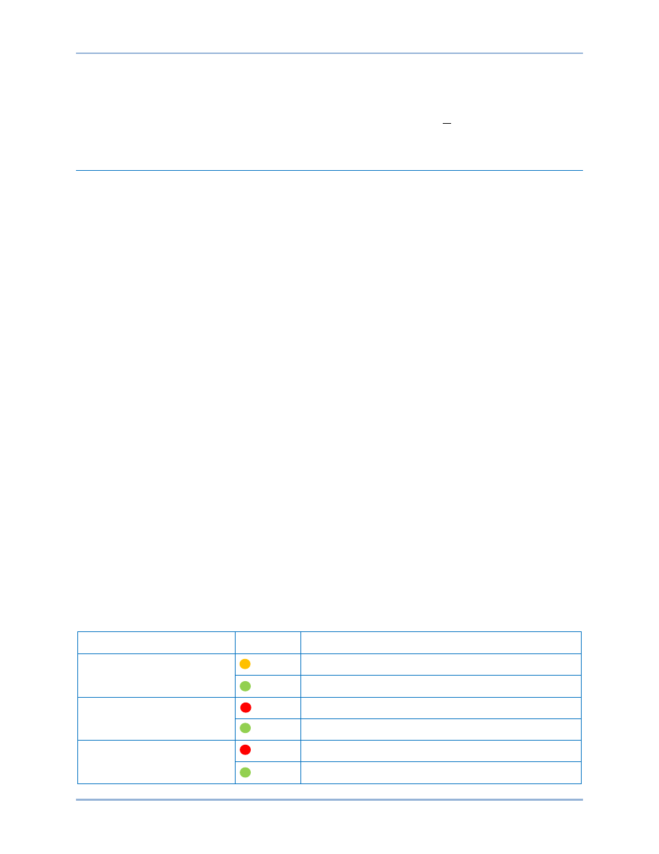
Three status LEDs are located in the lower right corner of the BESTlogicPlus window. These LEDs show
the Logic Save Status, Logic Diagram Status, and Logic Layer Status. Table 65 defines the colors for
each LED.
Table 65. Status LEDs
LED
Color
Definition
Logic Save Status
(Left LED)
Orange Logic has changed since last save.
Green Logic has NOT changed since last save.
Logic Diagram Status
(Center LED)
Red Requirements NOT met as listed above.
Green Requirements met as listed above.
Logic Layer Status
(Right LED)
Red Requirements NOT met as listed above.
Green Requirements met as listed above.
DGC-2020HD
BESTlogic
™Plus