Can interface, Figure 191, Aem-2020 – Basler Electric DGC-2020HD User Manual
Page 320
310
9469300990 Rev B
AEM-2020
DGC-2020HD
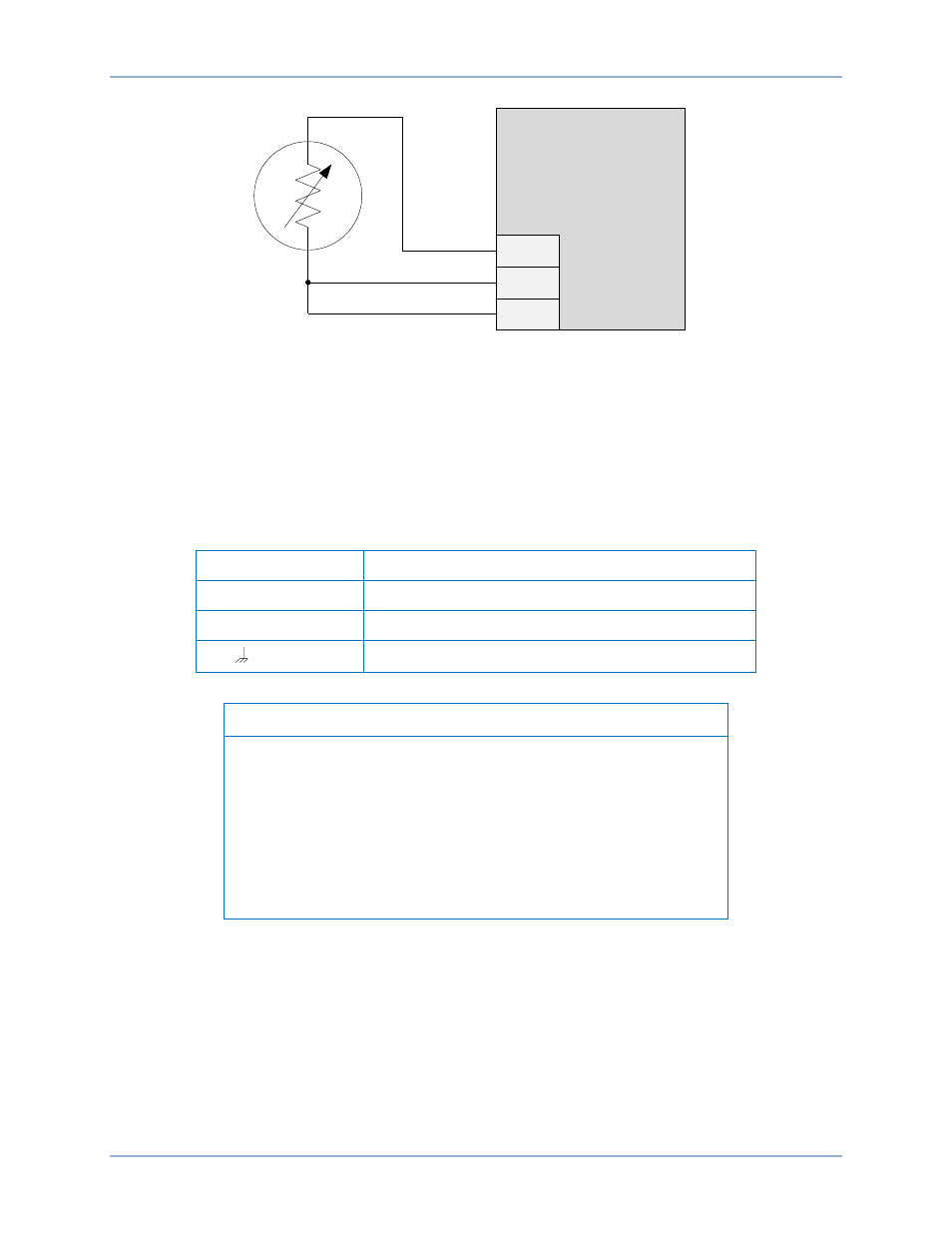
Figure 191. External Three-Wire RTD Input Connections
CAN Interface
These terminals provide communication using the SAE J1939 protocol and provide high-speed
communication between the Analog Expansion Module and the DGC-2020HD. Connections between the
AEM-2020 and DGC-2020HD should be made with twisted-pair, shielded cable. CAN interface terminals
are listed in Table 86. Refer to Figure 192 and Figure 193.
Table 86. CAN Interface Terminals
Terminal
Description
P1- HI (CAN H)
CAN high connection (yellow wire)
P1- LO (CAN L)
CAN low connection (green wire)
P1-
(SHIELD)
CAN drain connection
Notes
1.
If the AEM-2020 is providing one end of the J1939 bus, a 120
Ω,
½ watt terminating resistor should be installed across terminals
P1- LO (CANL) and P1- HI (CANH).
2.
If the AEM-2020 is not part of the J1939 bus, the stub connecting
the AEM-2020 to the bus should not exceed 914 mm (3 ft) in
length.
3.
The maximum bus length, not including stubs, is 40 m (131 ft).
4.
The J1939 drain (shield) should be grounded at one point only. If
grounded elsewhere, do not connect the drain to the AEM-2020.
RTD1+
RTD1
–
RTD1C
AEM-2020
P
0
0
5
3
-6
5
RED
BLACK
BLACK