Input type, Arming delay, Out-of-range alarm type – Basler Electric DGC-2020HD User Manual
Page 323: Ranges, Thresholds, Mode, Alarm configuration, Logic connections, Operational settings
9469300990 Rev B
313
DGC-2020HD
AEM-2020
If the threshold is set as an under threshold with 5% hysteresis, once the threshold detection trips, the
measured value must rise to 105% of the threshold before the threshold detection will drop out.
Input Type
A remote analog input can be configured to monitor a voltage or current signal.
Arming Delay
A user-adjustable arming delay disables remote analog input protection during engine startup. If the
arming delay is set to zero (0), the input protection is active at all times, including when the engine is not
running. If the arming delay is set to a non-zero value, the input protection is inactive when the engine is
not running, and does not become active until after the engine is started and the arming delay has
elapsed.
Out-of-Range Alarm Type
An out-of-range alarm alerts the user of an open or damaged remote analog input wire.
Ranges
Ranges must be set for the selected input type. Param Min correlates to Min Input Current or Min Input
Voltage and Param Max correlates to Max Input Current or Max Input Voltage.
Thresholds
There are four programmable thresholds for each remote analog input element. Each threshold has a
mode setting, threshold setting, activation delay setting, and an alarm setting.
Mode
The mode can be set for Over or Under. If Over mode is selected, an alarm is annunciated when the
metered input increases above the Threshold setting for the duration of the Activation Delay. If Under
mode is selected, an alarm is annunciated when the metered input decreases below the Threshold setting
for the duration of the Activation Delay.
Alarm Configuration
Each remote analog input protection threshold item can be independently configured to annunciate an
alarm or pre-alarm, or be configured as status only when the metered input falls beyond the threshold. A
user-adjusted activation delay setting delays alarm annunciation until after the threshold has been
exceeded. Remote a
nalog input protection is disabled when Alarm Configuration is set to “None”.
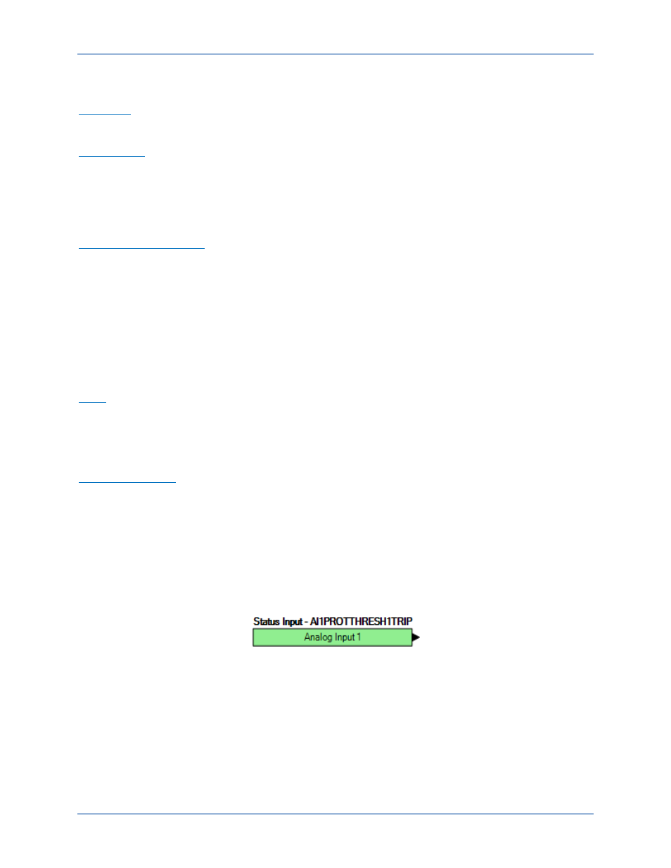
Logic Connections
Remote analog input protection logic connections are made on the BESTlogicPlus screen in
BESTCOMSPlus. The Analog Input 1, Threshold 1 logic block is illustrated in Figure 195. The output is
true during a trip condition. The alarm and pre-alarm logic blocks are similar.
Figure 195. Remote Analog Input Protection Logic Block
Operational Settings
Remote analog input protection operational settings are configured on the AEM x Input #y (where x = 1 to
4 and y = 1 to 8) settings screen (Figure 196) in BESTCOMSPlus.