Generator and mains breaker control, Load, Dgc-2020hd – Basler Electric DGC-2020HD User Manual
Page 88
78
9469300990 Rev B
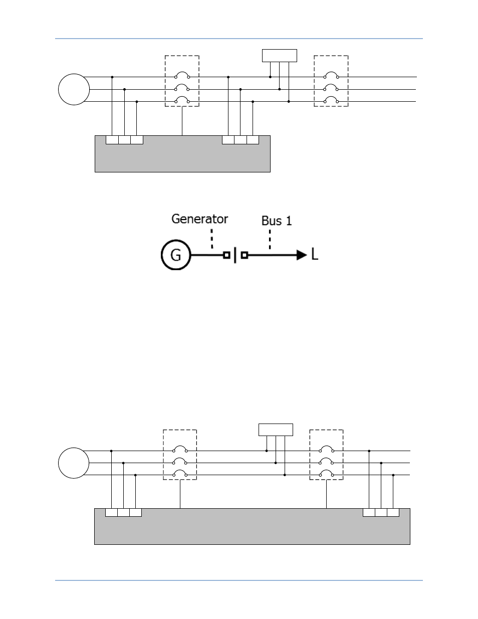
Figure 33. System Breaker Configuration: Generator Breaker Control with Externally Controlled Mains
Breaker
Figure 34. System Breaker Configuration: Generator Breaker Control as Displayed in BESTCOMSPlus
System Settings.
Generator and Mains Breaker Control
Generator and Mains Breaker Control system breaker configurations consist of two breakers controlled by
the DGC-2020HD. Figure 35 illustrates a Generator And Mains Breaker Control system breaker
configuration without optional load bus metering. Figure 36 illustrates the one-line diagram of the
Generator And Mains Breaker Control system breaker configuration as it appears in the BESTCOMSPlus
System Settings screen. Figure 37 shows the same configuration with optional load bus metering. Figure
38 illustrates the one-line diagram of the Generator And Mains Breaker Control system breaker
configuration as it appears in the BESTCOMSPlus System Settings screen. Optional load bus metering,
provides more precise control over breaker closures. DGC-2020HD units must be equipped with
enhanced bus sensing (style number xxxxxxxEx) in order to meter all three buses.
Figure 35. System Breaker Configuration: Generator and Mains Breaker Control
Generator
Generator
Breaker
L1
L2
L3
Generator Bus
Load Bus
Generator
Bus Metering
P0071-78
LOAD
Mains
Breaker
Mains Bus
A
B
C
Generator
Breaker
Control Output
86
88
90
93
95
97
Bus 1
DGC-2020HD
Load Bus
Metering
Generator
Generator
Breaker
L1
L2
L3
Generator Bus
Load Bus
Generator
Bus Metering
P0071-72
LOAD
Mains
Breaker
Mains Bus
Mains Bus
Metering
A
B
C
Generator
Breaker
Control Output
Mains Breaker
Control Output
86
88
90
93
95
97
Bus 1
DGC-2020HD
Breaker Management
DGC-2020HD