Basler Electric DGC-2020HD User Manual
Page 241
9469300990 Rev B
231
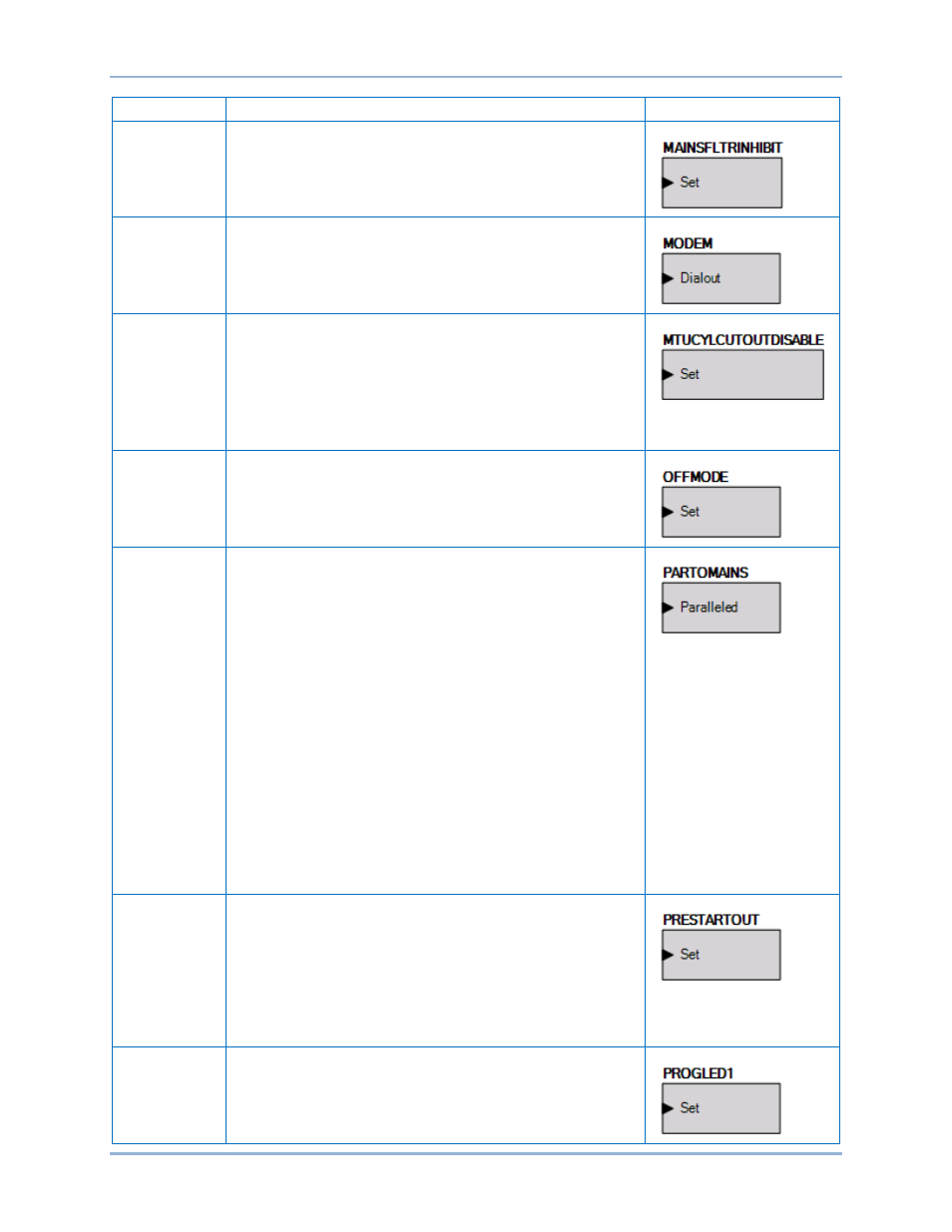
Name
Description
Symbol
Mains Fail
Transfer Inhibit
The mains fail transfer function is inhibited when the Set input is
true.
Modem Control
Connect the Dialout input to the output of another logic block.
When true, the modem will dial out.
MTU Cylinder
Cutout Disable
When the Set input is true, Cylinder Cutout Disable 1 and
Cylinder Cutout Disable 2 are both sent to the engine ECU with
true status. When this logic element is false, Cylinder Cutout
Disable 1 and Cylinder Cutout Disable 2 are sent to the engine
ECU with states set by the values programmed for the Cylinder
Cutout Disable 1 and Cylinder Cutout Disable 2 DGC-2020HD
settings which are configured on the ECU Setup screen in
BESTCOMSPlus.
Off Mode
When the Set input is true, the DGC-2020HD will switch to OFF
mode. This is a pulsed input. It does not need to be held after
the desired mode switch has occurred.
Paralleled to
Mains
Setting the Paralleled input to true indicates to the DGC-2020HD
that it is paralleled to a utility.
When paralleled to the utility, the kW controller will regulate the
machine’s kW output at the Base Load Level (%) that is set on
the Governor Bias Control Settings screen, where the Base
Load Level is in percent of the machine’s rated kW. Otherwise,
the kW controller will implement kW load sharing when part of a
load sharing system. If a load sharing system is not
implemented, the speed controller can be set up to implement
speed droop.
When paralleled to the utility, the var/PF controller will regulate
the machine’s reactive power output according to the control
mode setting. If the control mode is var Controller, the output will
be regulated to the kvar Setpoint (%) that is set on the AVR Bias
Control Settings screen, where the kvar Setpoint (%) is in
percentage of the machines rated kvar. If the control mode is PF
Control, the reactive power output is regulated to a level that
maintains the machines power factor at the value specified by
the PF setting on the AVR Bias Control Settings screen. When
var/PF control is not active or not enabled, the voltage controller
can be set up to implement voltage droop.
Prestart Output
This element is used to drive the prestart output relay from logic
when the Prestart Output Relay configuration is set to
“Programmable”. When the Prestart Output Relay configuration
is set to “Programmable”, the prestart relay will not close unless
logic is used to drive this element. When the Prestart Output
Relay configuration is set to “Predefined”, the prestart relay is
closed according to the predefined prestart functionality of the
DGC-2020HD. When the “Predefined” functionality is selected,
the relay will not respond to this element.
Programmable
LED x
When the Set input is true, this element illuminates
Programmable LED x on the front panel.
DGC-2020HD
BESTlogic
™Plus