Logic connections – Basler Electric DGC-2020HD User Manual
Page 79
9469300990 Rev B
69
Table 32. Settings for Analog Inputs
Locator
Setting
Range
Increment
Unit
Input Setup
A
Label Text
16 alphanumeric
characters
n/a
n/a
B
Hysteresis
0 to 100
0.1
%
C
Input Type
Voltage or Current
n/a
n/a
D
Arming Delay
0 to 300
1
seconds
E
Out of Range Alarm Type
Status Only, Pre-
Alarm, or Alarm
n/a
n/a
Ranges
F
Param Min
-999,999 to 999,999
varies
n/a
G
Param Max
-999,999 to 999,999
varies
n/a
H
Min Input Current
4 to 20
0.1
milliamps
I
Max Input Current
4 to 20
0.1
milliamps
J
Min Input Voltage
-10 to 10
0.1
volts
K
Max Input Voltage
-10 to 10
0.1
volts
Threshold Settings 1 to 4
L
Mode
Disabled, Over, or
Under
n/a
n/a
M
Threshold
-999,999 to 999,999
0.01
n/a
N
Activation Delay
0 to 300
1
seconds
O
Alarm Configuration
Status Only, Pre-
Alarm, or Alarm
n/a
n/a
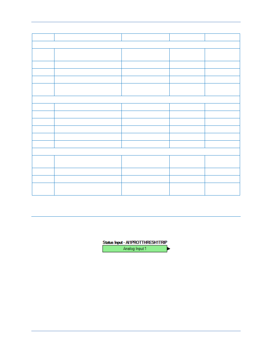
Logic Connections
Analog input protection logic connections are made on the BESTlogicPlus screen in BESTCOMSPlus.
The Analog Input 1, Threshold 1 logic block is illustrated in Figure 27. The output is true during a trip
condition. The alarm and pre-alarm logic blocks are similar.
Figure 27. Analog Input Protection Logic Block
DGC-2020HD
Analog Inputs