Generator network status display – Basler Electric DGC-2020HD User Manual
Page 57
9469300990 Rev B
47
controls are displayed at the bottom. To send a breaker open or breaker close request, select the
appropriate menu option and press Edit.
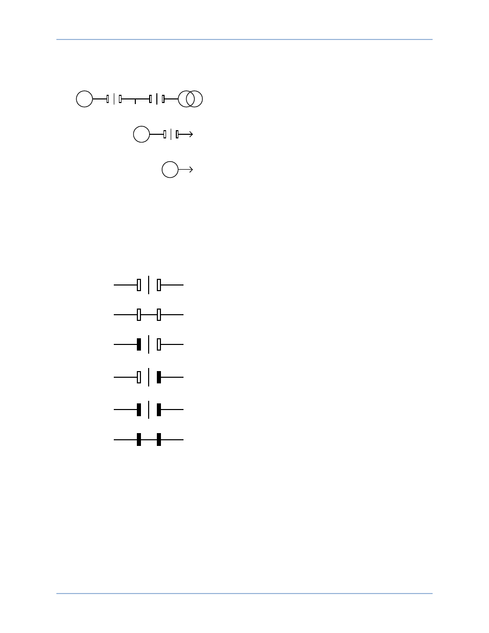
Figure 17, below, illustrates the different configurations of the one-line diagram.
Generator and Mains Breakers with Load Sensing
Generator and Mains Breakers
Generator Breaker
None
Figure 17. System Configuration One-Line Diagrams
The diagrams in Figure 17 show all breakers in the open position and all buses in a dead/unstable state.
Breaker and bus states in the diagram change in real time to reflect the actual breaker and bus status.
When a breaker is open, the line between the contacts is vertical and when closed the line is horizontal. A
stable bus is indicated by a filled rectangle and a bus in any state other than stable is indicated by an
unfilled rectangle. See Figure 18 for the different breaker and bus states.
Breaker open
Both buses dead/unstable
Breaker closed
Both buses dead/unstable
Breaker open
One bus stable and the other dead/unstable
Breaker open
One bus stable and the other dead/unstable
Breaker open
Both buses stable
Breaker closed
Both buses stable
Figure 18. One-Line Diagram Breaker and Bus States
Generator Network Status Display
The status of the generator network is available on the front panel of each DGC-2020HD when the
generator is part of a multi-machine network. The System Type setting (found in the BESTCOMSPlus
®
Settings Explorer, System Parameters, System Settings) configures the machine to be part of a multi-
machine network. When System Type is set to Multiple Generator, the machine is configured for
participation in a multiple machine system.
Generator network status is found on the front panel under Metering, Status, Gen Network Status.
G
L
G
L
G
L
P0071-90
P0071-91
DGC-2020HD
Controls and Indicators