Voltage regulator setup – Basler Electric DGC-2020HD User Manual
Page 262
252
9469300990 Rev B
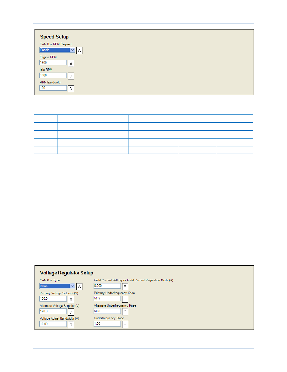
Figure 159. Settings Explorer, Communications, CAN Bus, Speed Setup
Table 72. Settings for Speed Setup
Locator
Setting
Range
Increment
Unit
A
CAN Bus RPM Request
Disable or Enable
n/a
n/a
B
Engine RPM
750 to 3,600
1
RPM
C
Idle RPM
100 to 2,000
1
RPM
D
RPM Bandwidth
0 to 1,000
1
n/a
Voltage Regulator Setup
BESTCOMSPlus
®
Navigation Path: Settings Explorer, Communications, CAN Bus Setup, Voltage
Regulator Setup
HMI Navigation Path: Settings, Communication > CAN Bus 2 (ECU) Setup > ECU Setup > Voltage
Regulator Setup
The DGC-2020HD transmits voltage setpoint and underfrequency compensation parameters to a
connected voltage regulator. Select the appropriate CAN bus type being used: None, Marathon, Basler,
or J1939. The Primary Voltage Setpoint value represents the normal desired system voltage setpoint.
Alternate Voltage Setpoint becomes the active system voltage setpoint when low line override is true. The
range in which the DGC-2020HD biases voltage regulator var sharing and voltage trim is dictated by the
Voltage Adjust Bandwidth setting. When the voltage regulator is in Field Current Regulation (FCR) mode,
the normal desired field current setpoint is set using the Field Current Setting for Field Current Regulation
Mode. The Primary Underfrequency Knee setting allows adjustment of the normal desired
underfrequency knee-point. When low line override is true, the Alternate Underfrequency Knee becomes
the active underfrequency knee-point. The desired Underfrequency slope can also be specified.
Figure 160 illustrates the BESTCOMSPlus Voltage Regulator Setup screen. Settings are listed in Table
73.
Figure 160. Settings Explorer, Communications, CAN Bus, Voltage Regulator Setup
Communication
DGC-2020HD