Logic connections, Operational settings, Setting groups – Basler Electric DGC-2020HD User Manual
Page 159: Setting group functions
9469300990 Rev B
149
Logic Connections
Loss of excitation logic connections are made on the BESTlogicPlus screen in BESTCOMSPlus. The loss
of excitation element logic block is illustrated in Figure 85. When the Block input is true, the 40Q element
is disabled. The Trip output is true when the 40Q element is in a trip condition.
Figure 85. Loss of Excitation Element Logic Block
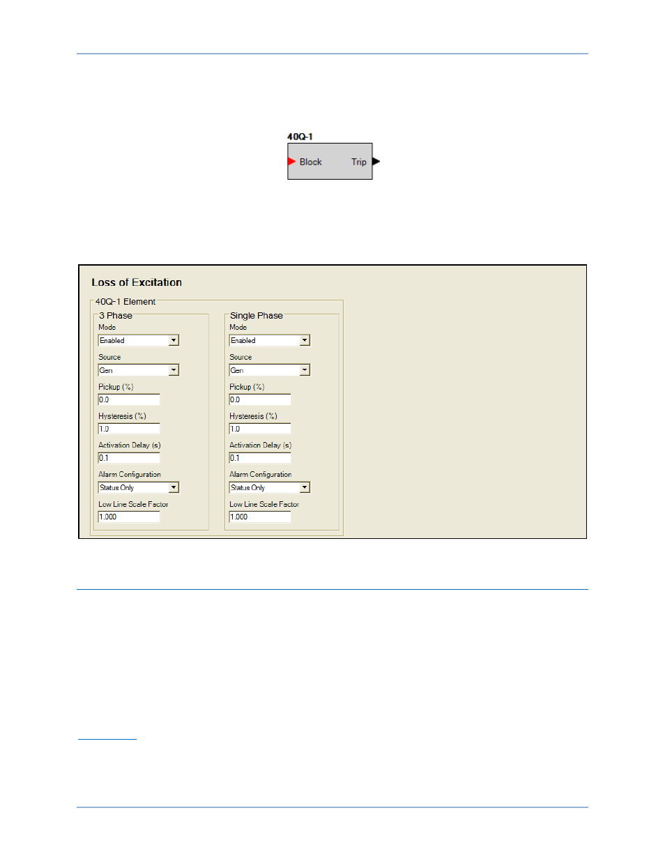
Operational Settings
Loss of Excitation element operational settings are configured on the Loss of Excitation settings screen
(Figure 86) in BESTCOMSPlus. Setting ranges are defined in the Specifications chapter.
Figure 86. Settings Explorer, Generator Protection, Power, Loss of Excitation
Setting Groups
Four setting groups allow for adapting the coordination settings to optimize them for a predictable
situation.
These four setting groups are designated Setting Group 0, Setting Group 1, Setting Group 2, and Setting
Group 3. Setting group logic connections are made on the BESTlogicPlus screen in BESTCOMSPlus.
Setting Group Functions
The group of settings that is active at any point in time is controlled by setting group selection logic. This
function logic allows for manual (logic) selection.
Logic Inputs
This function monitors logic inputs D0 through D3 and changes the active setting group according to the
status of these three inputs. These inputs can be connected to logic expressions such as contact sensing
outputs.
DGC-2020HD
Generator Protection