H3C Technologies H3C MSR 50 User Manual
Page 547
162
After that the administrator starts to collect topology information. Note that, in addition to manual
topology collection, the system automatically collects topology information every minute.
3.
Click Network Snapshot to save the current WiNet topology as the baseline topology. The
baseline topology is used to show changes in network topology at different time points.
4.
Click Initialize Topology to clear the stored baseline topology and cookies.
5.
Click Open AuthN Center to configure a RADIUS server for security authentication on the
administrator device. The administrator device automatically generates a guest user guest and its
password and updates the user and password at 24:00.
6.
After the authentication center starts up, the Open AuthN Center button changes to Close AuthN
Center. Click the Close AuthN Center to remove the RADIUS server and the guest user.
7.
Drag the icon of a specific device in the WiNet topology and place it to a position as needed. If
the browser is configured to accept cookies, the latest position information of each device is stored
after you click Network Snapshot.
8.
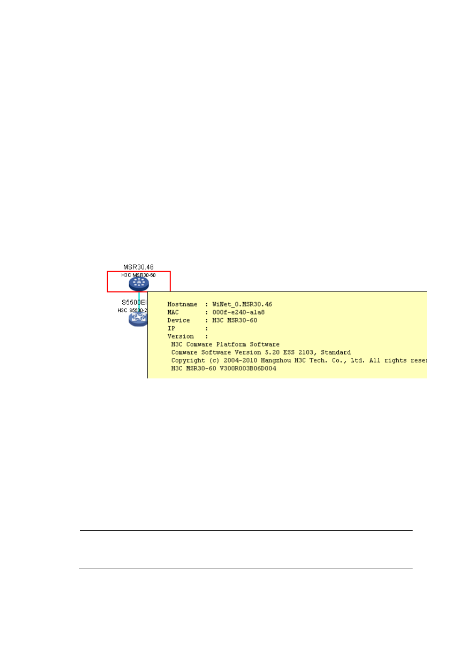
Double-click a device on the WiNet topology map to show details about the device, including the
hostname, MAC address, device model, IP address, version, number of hops, and WiNet
.
Figure 551 Device details
9.
View the WiNet topology information, including the role of each device and connection status
between devices. The connection status can be:
Normal link—Indicates a connection existing in the baseline topology and the current topology.
New link—Indicates a connection not existing in the baseline topology but in the current
topology.
Blocked loops—Indicate connections blocked by STP. If a normal link is blocked, it is displayed
as a black broken line; if a new link is blocked, it is displayed as a blue broken line.
Down link—Indicates a connection existing in the baseline topology but not in the current
topology.
10.
Click a device in the topology diagram to view its panel diagram. You can manage the device as
follows:
NOTE:
Support for displaying of the device panel, device renaming, and Layer 2 portal authentication on
interfaces depends on the device model.
a.
Click Rename Device and enter a new system name for the device.