Configure router c – H3C Technologies H3C MSR 50 User Manual
Page 617
232
1.
Configure a local number: specify the local number ID as 2000 and the number as 2000, and
bind the number to line line 1/0 on the local number configuration page.
2.
Configure the call route to Router A: specify the call route ID as 1000, the destination number as
1000, and the call route type as SIP, and use a SIP proxy server to complete calls on the call route
configuration page.
3.
Configure the call route to Router C: specify the call route ID as 3000, the destination number as
3000, and the call route type as SIP, and use a proxy server to complete calls on the call route
configuration page.
4.
Configure SIP registration: enable register function of the server on the connection properties
configuration page. Select Voice Management > Call Connection > SIP Connection from the
navigation tree to access the connection properties configuration page, then configure the IP
addresses of both the main registrar and the proxy server as 100.1.1.101.
Configure Router C
# Configure a local number and call routes.
1.
Configure a local number: specify the local number ID as 3000 and the number as 3000, and
bind the number to line line 1/0 on the local number configuration page.
2.
Configure the call route to Router A: specify the call route ID as 1000, the destination number as
1000, and the call route type as SIP, and use a SIP proxy server to complete calls on the call route
configuration page.
3.
Configure the call route to Router B: specify the call route ID as 2000, the destination number as
2000, and the call route type as SIP, and use a proxy server to complete calls on the call route
configuration page.
4.
Configure SIP registration: enable register function of the server on the connection properties
configuration page. Select Voice Management > Call Connection > SIP Connection from the
navigation tree to access the connection properties configuration page, then configure the IP
addresses of both the main registrar and the proxy server as 100.1.1.101.
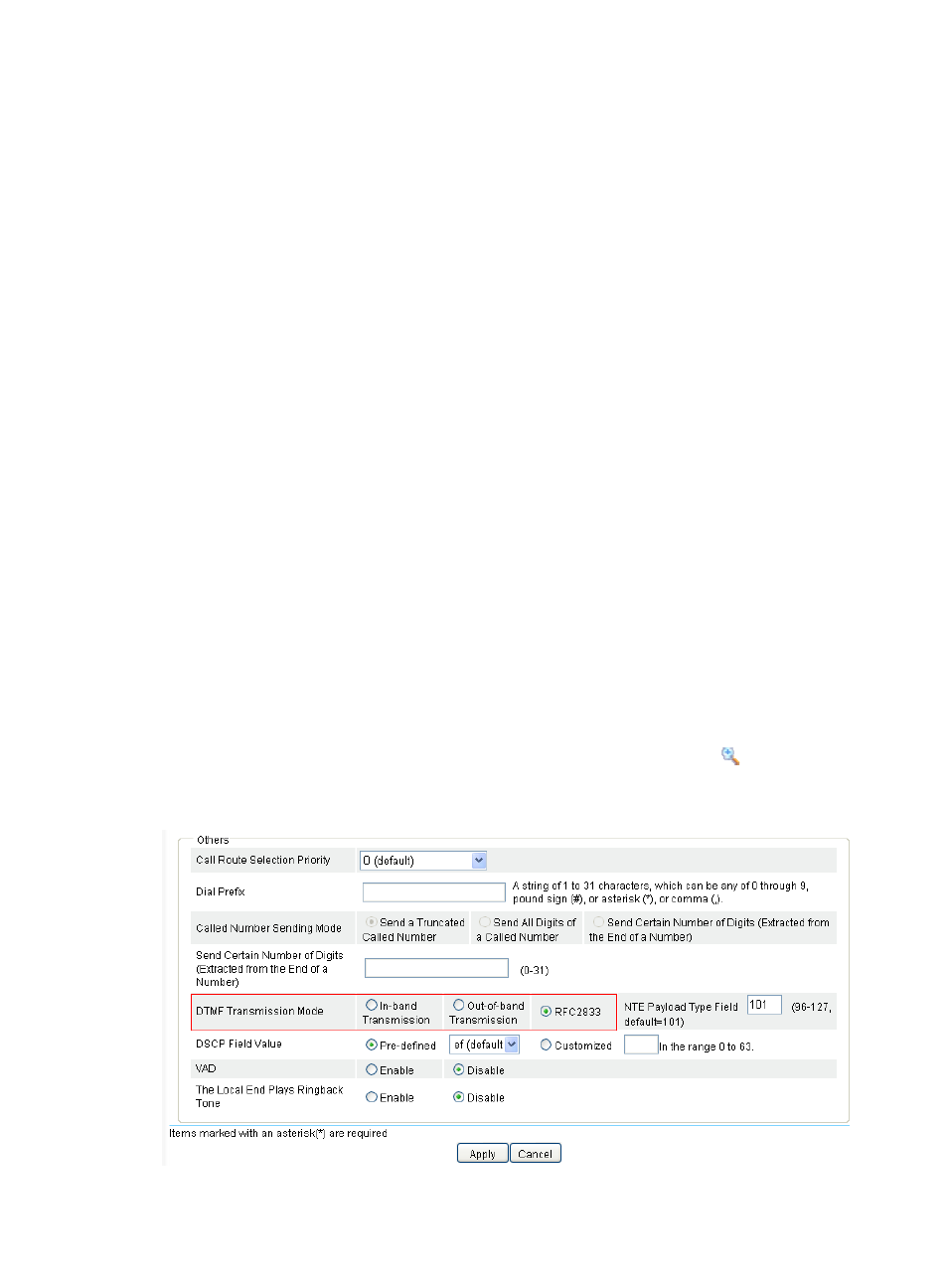
# Configure the DTMF transmission mode as out-of-band transmission.
5.
Select Voice Management > Call Route from the navigation tree and click the
icon of call route
1000 to access the advanced settings page as shown in
Figure 621 Configuring DTMF transmission mode