13 inverter protection, 14 motor protection – Watson-Marlow MM440 User Manual
Page 108
3 Functions
Issue 10/06
MICROMASTER 440 Operating Instructions
108
6SE6400-5AW00-0BP0
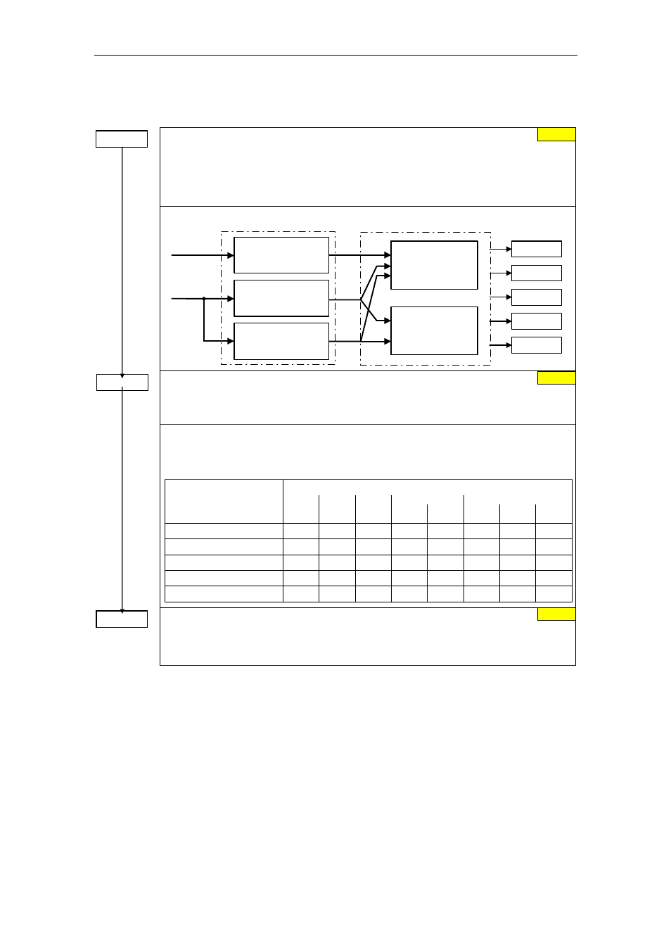
3.5.7.13 Inverter
protection
Inverter overload reaction
Selects reaction of inverter to an internal over-temperature.
0 Reduce output frequency
1 Trip (F0004 / F0005)
2 Reduce pulse frequency and output frequency
3 Reduce pulse frequency then trip (F0004)
A0504
A0505
A0506
F0004
F0005
Inverter overload reaction
P0290
f_pulse
control
i_max control
(U/f)
Current control
(SLVC, VC)
r0036
r0037
Heat sink
temperature
P0292
IGBT
temperature
P0292
i
2
t
P0294
Inverter monitoring
P0292 =...
Inverter temperature warning
Defines the temperature difference (in ºC) between the Overtemperature trip threshold and
the warning threshold of the inverter. The trip threshold is stored internally by the inverter
and cannot be changed by the user.
Temperature
MM440, Frame Size
110 °C
140 °C
95 °C
145 °C
A - C
D - F
Input rectifier
-
Cooling air
-
Control board
-
80 °C
145 °C
F
600 V
-
-
-
-
-
-
88 °C
150 °C
FX
95 kW
CT
91 °C
150 °C
110 kW
CT
75 °C
55 °C
75 °C
55 °C
65 °C
65 °C
80 °C
145 °C
GX
132 kW
CT
82 °C
147 °C
160 kW
CT
75 °C
55 °C
75 °C
55 °C
65 °C
65 °C
88 °C
150 °C
200 kW
CT
75 °C
50 °C
65 °C
IGBT
Heat sink
trip
T
= T
- P0292
Temperature warning threshold of inverter T_warn
Temperature shutdown threshold of inverter T_trip
warn
Delay, fan shutdown
This defines the delay time in seconds between powering down the frequency inverter and
then powering-down the fan. A setting of 0 means that the fan is immediately shut down
(powered-down).
3.5.7.14 Motor
protection
In addition to the thermal motor protection, the motor temperature is also included
in the adaptation of the motor equivalent circuit diagram data. Especially for a high
thermal motor load, this adaptation has a significant influence on the degree of
stability of the closed-loop vector control. For MM440 the motor temperature can
only be measured using a KTY84 sensor. For the parameter setting P0601 = 0,1,
the motor temperature is calculated / estimated using the thermal motor model.
If the frequency inverter is permanently supplied with an external 24V voltage, then
the motor temperature is also tracked/corrected using the motor temperature time
constant – even when the line supply voltage is switched-out.
0 s
P0295 = ...
p0290 = ...
0
15 °C