Compound braking – Watson-Marlow MM440 User Manual
Page 123

Issue 10/06
3 Functions
MICROMASTER 440 Operating Instructions
6SE6400-5AW00-0BP0
123
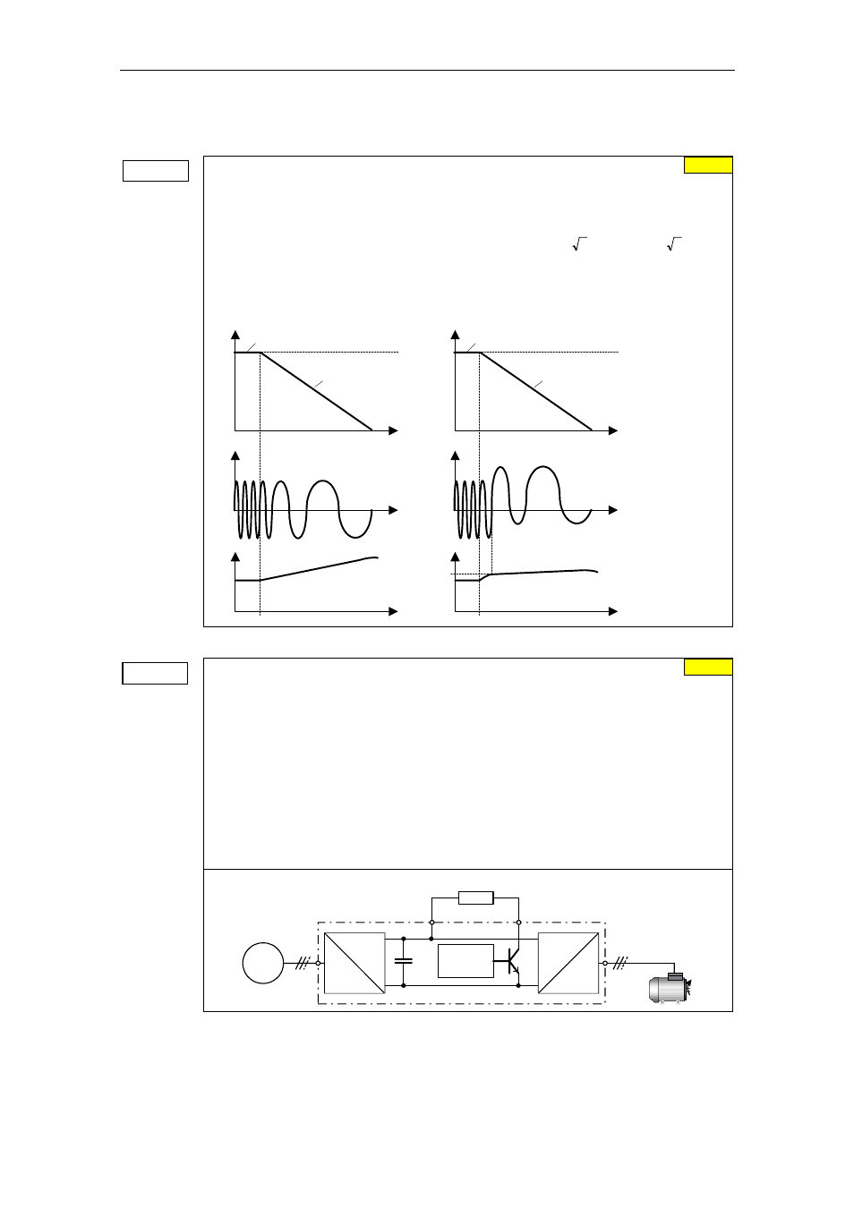
Compound braking
P1236 =...
Compound braking current
(entered in %)
Defines DC level superimposed on AC waveform after exceeding DC-link voltage threshold
of compound braking. The value is entered in [%] relative to rated motor current (P0305).
(see also
Vdc controller ").
Compound braking switch-on level
P0210
2
13
.
1
V
2
1.13
U
mains
DC_Comp
⋅
⋅
=
⋅
⋅
=
If P1254 = 0 :
1242
r
0.98
U
DC_Comp
⋅
=
Compound braking switch-on level
otherwise :
⏐f⏐
i
t
t
f_act
f_set
P1236 = 0
Without Compound braking
u
t
⏐f⏐
i
t
t
f_act
f_set
P1236 > 0
With Compound braking
t
DC-link
u
DC-link
U
DC_Comp
Dynamic braking
Dynamic braking
Dynamic braking is activated using parameter P1237 – the nominal (rated) duty cycle as
well as the switch-in duration of the braking resistor are also defined.
0 Inhibited
1 Load duty cycle 5 %
2 Load duty cycle 10 %
3 Load duty cycle 20 %
4 Load duty cycle 50 %
5 Load duty cycle 100 %
Using the dynamic brake, the regenerative feedback energy is transferred to the external
braking resistor using the chopper control (braking chopper); it is converted into thermal
energy (heat) in this resistor. This dynamic braking allows the drive to be braked in a
controlled fashion. This function is not available for sizes FX and GX.
Chopper resistor
Chopper
control
B-
=
~
~
B+
=
~
MM4
P1237 = ...
0
0 %