Watson-Marlow MM440 User Manual
Page 208
3 Functions
Issue 10/06
MICROMASTER 440 Operating Instructions
208
6SE6400-5AW00-0BP0
The regenerative (braking) energy is converted into thermal energy using the
chopper resistor. A braking module (chopper control) is integrated in the DC link for
this purpose. The chopper of the braking module switches the resistor with a mark-
space ratio corresponding to the regenerative power to be dissipated. The braking
module is only active if, as a result of the regenerative operation, the DC link
voltage lies above the chopper switch-in threshold V
DC chopper
. This means that the
braking module is not active in normal operation when motoring.
The chopper resistor is only designed for a specific power and a certain load duty
cycle and can only absorb a limited amount of braking energy within a specific time
period. The chopper resistors, specified in MICROMASTER Catalog DA51.2, have
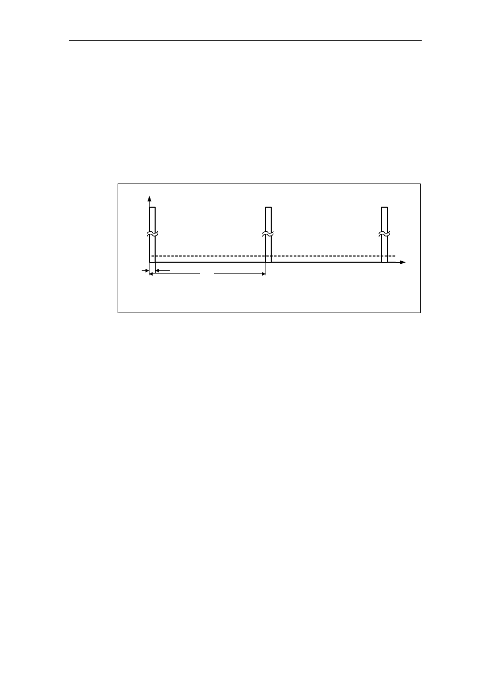
the following load duty cycle.
Power
0.05
t [s]
12
240
P
DB
1
P
100
P
DB
P
100
= continuous power
= permissable power for 12 s every 240 s
DB
P
20
=
⋅
Fig. 3-78
Load duty cycle – chopper resistors (MICROMASTER Catalog DA51.2)
This load duty cycle (P1237 = 1
→ 5 %) is saved in MICROMASTER. If the values
are exceeded due to the load required, then when the maximum acceptable
braking energy is reached, the load duty cycle monitoring controls the chopper so
that the value is reduced to the value entered in parameter P1237. This means that
the energy to be dissipated in the chopper resistor is reduced which means that the
DC link voltage quickly increases due to the regenerative energy available and the
drive inverter is shutdown (tripped) due to a DC link overvoltage condition.
If the continuous power or the load duty cycle for a resistor is too high, then the
continuous rating can be quadrupled using 4 resistors in a bridge circuit
configuration. In this case, in addition, the load duty cycle must be increased using
parameter P1237 from P1237 = 1 (
→ 5 %) to P1237 = 3 (→ 20 %). When using
the bridge circuit, the overtemperature switch of the resistors should be connected
in series and incorporated in the fault circuit. This guarantees, that when a resistor
overheats, the complete system / drive inverter is shut down.