2 operator panels for micromaster, 1 description of the bop (basic operator panel) – Watson-Marlow MM440 User Manual
Page 70
3 Functions
Issue 10/06
MICROMASTER 440 Operating Instructions
70
6SE6400-5AW00-0BP0
3.2
Operator panels for MICROMASTER
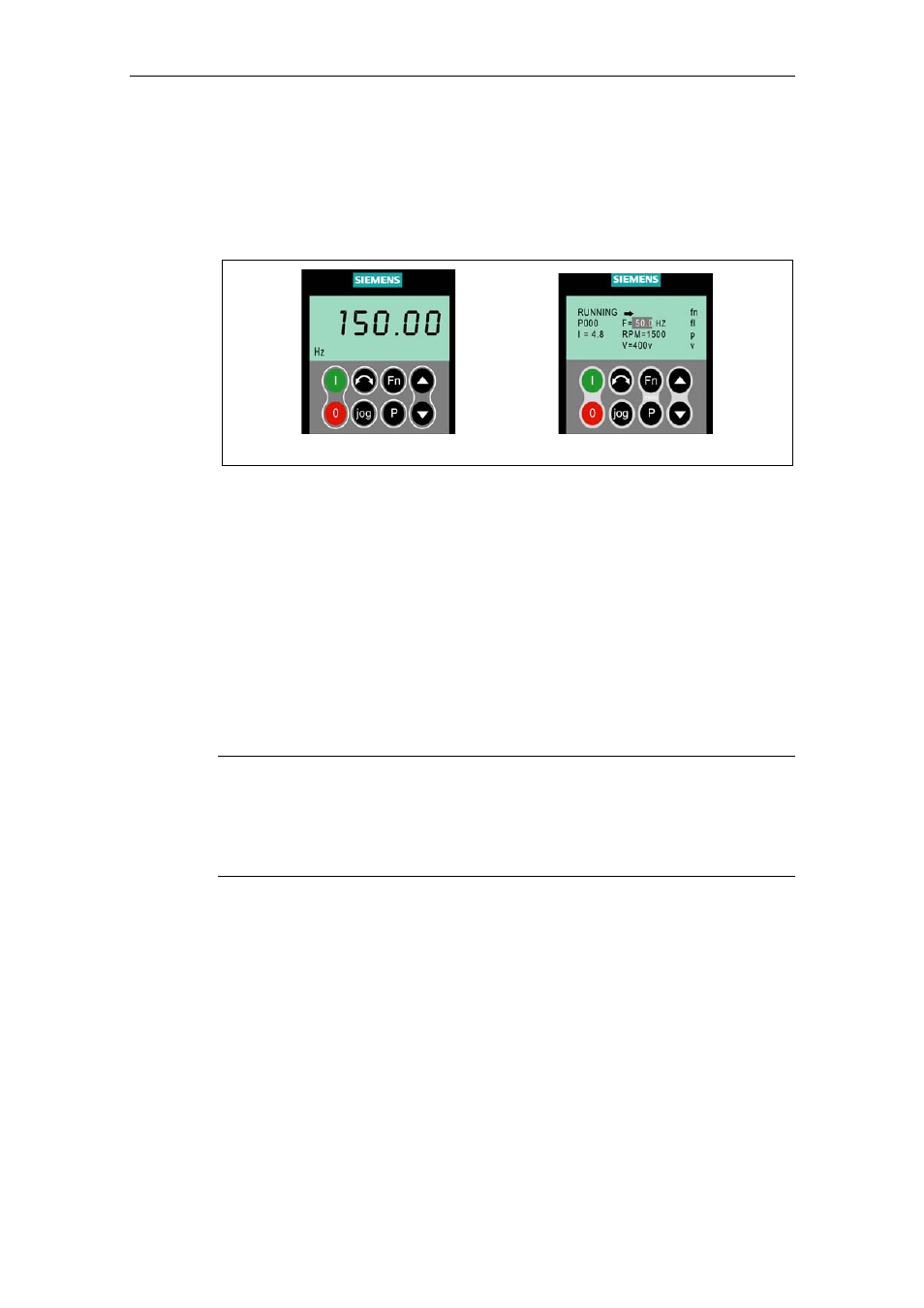
MICROMASTER drive units can be optionally equipped with a BOP (Basic
Operator Panel) or AOP (Advanced Operator Panel). The AOP distinguishes itself
as a result of a plain text display which simplifies operator control, diagnostics as
well as also commissioning (start-up).
BOP AOP
Fig. 3-14
Operator panels
3.2.1
Description of the BOP (Basic Operator Panel)
The BOP, available as option, allows drive inverter parameters to be accessed. In
this case, the Status Display Panel (SDP) must be removed and the BOP either
inserted or connected in the door of a cabinet using a special mounting kit
(Operator panel door mounting set) (refer to the Attachment A).
Parameter values can be changed using the BOP. This allows the
MICROMASTER drive unit to be set-up for a particular application. In addition to
the keys (refer to Section 3.2.3), it includes a 5-digit LCD display on which the
parameter numbers rxxxx and Pxxxx, parameter values, parameter units (e.g. [A],
[V], [Hz], [s]), alarm Axxxx or fault messages Fxxxx as well as setpoints and actual
values.
NOTE
¾
Contrary to the AOP, for the BOP, parameters do not have to be set or taken
into consideration when establishing the communications between the BOP and
drive inverter.
¾
A BOP does not have a local memory. This means that it is not possible to save
a parameter set on the BOP.