2 power and motor connections – Watson-Marlow MM440 User Manual
Page 35
Issue 10/06
2 Installation
MICROMASTER 440 Operating Instructions
6SE6400-5AW00-0BP0
35
2.4.2
Power and motor connections
WARNING
The inverter must always be grounded.
♦ Isolate the mains electrical supply before making or changing connections to
the unit.
♦ Ensure that the inverter is configured for the correct supply voltage:
MICROMASTERS must not be connected to a higher voltage supply.
♦ When synchronous motors are connected or when coupling several motors in
parallel, the inverter must be operated with V/f control characteristic (P1300 =
0, 2 or 3).
CAUTION
After connecting the power and motor cables to the proper terminals, make sure
that the front covers have been replaced properly before supplying power to the
unit!
NOTICE
♦ Ensure that the appropriate circuit-breakers/fuses with the specified current
rating are connected between the power supply and inverter (see chapter 5,
Tables 5-5).
♦ Use Class 1 60/75
o
C copper wire only (for UL compliance). For tightening
torque see Table 5-2.
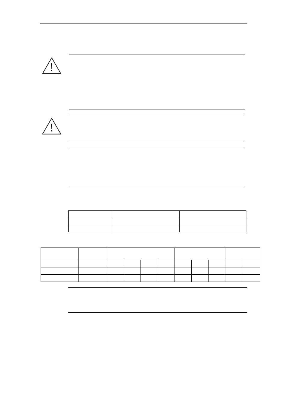
Operation with long cables
All inverters will operate at full specification with cable lengths as follows:
Frame Sizes
A to F
FX and GX
screened
50 m
100 m
unscreened
100 m
150 m
Using the output chokes specified in catalogue DA 51.2, the following cable lengths
are possible for the appropriate frame sizes:
Supply Voltage
200 V …
240 V ± 10%
380 V … 400 V ± 10 %
401 V … 480 V ± 10 %
500 V … 600 V
± 10%
Frame Sizes
A … F
A … B
C
D … F FX, GX A … C
D … F FX, GX
C
D … F
screened
200 m
150 m 200 m
200 m
300 m 100 m 200 m 300 m 100 m 200 m
unscreened
300 m
225 m 300 m 300 m 450 m 150 m 300 m 450 m 150 m 300 m
CAUTION
If using output chokes operation is only permissible with a pulse frequency of
4 kHz. Make shure that the automatic pulse frequency reductions are disabled.
Coercing required parameter adjusting: P1800 = 4 kHz , P0290 = 0 or 1.