3 analog inputs (adc) – Watson-Marlow MM440 User Manual
Page 140

3 Functions
Issue 10/06
MICROMASTER 440 Operating Instructions
140
6SE6400-5AW00-0BP0
3.6.3
Analog inputs (ADC)
Number: 2
Parameter range:
P0750 – P0762
Function chart number:
FP2200
Features:
- cycle time:
4 ms
- resolution:
10 bits
- accuracy:
1 % referred to 10 V / 20 mA
- electrical features:
incorrect polarity protection, short-circuit proof
Analog setpoints, actual values and control signals are read-into the drive inverter
using the appropriate analog inputs and are converted into digital signals / values
using the ADC converter.
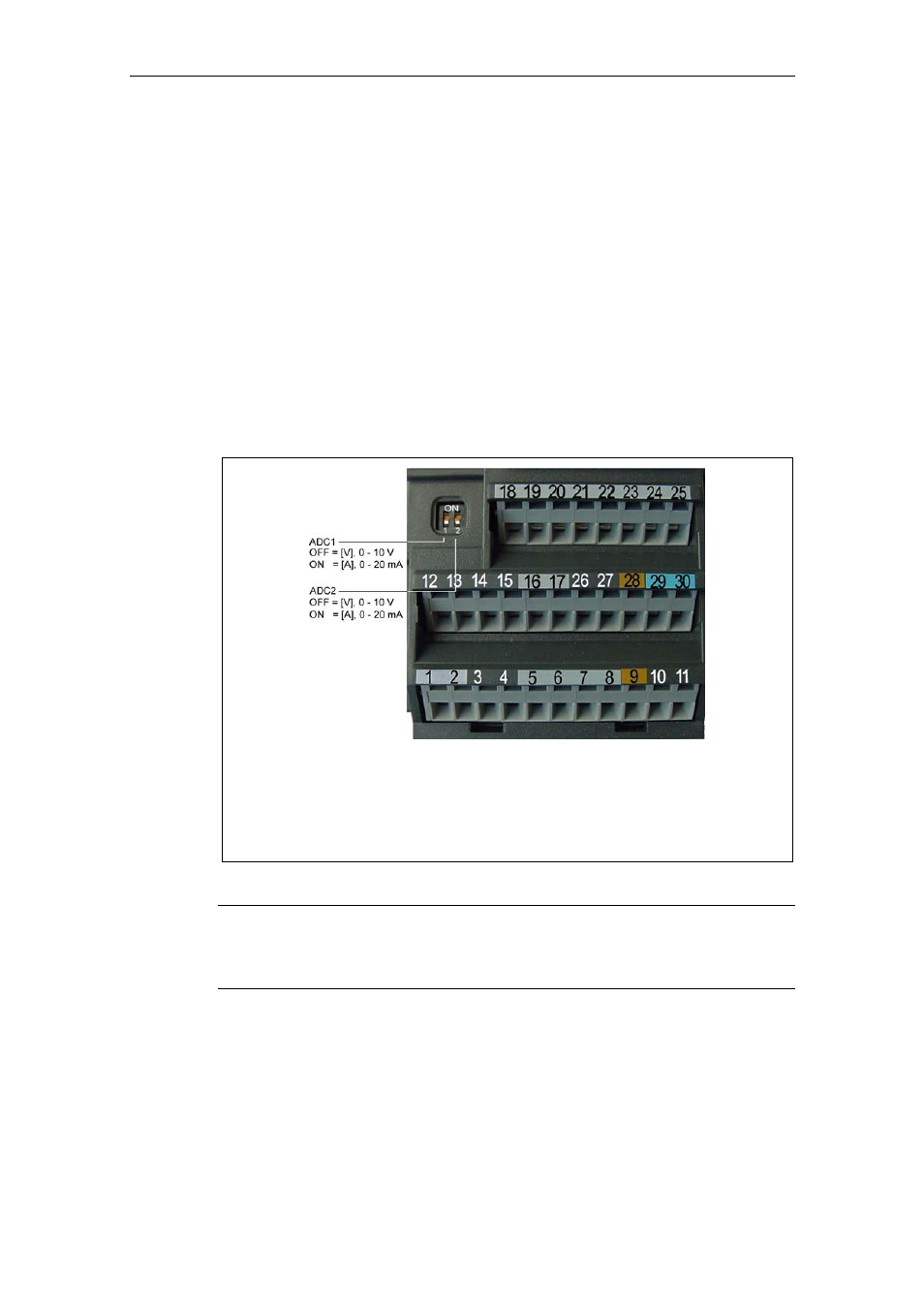
The setting as to whether the analog input is a voltage input (10 V) or a current
input (20 mA) must be selected using the 2 switches DIP1(1,2) on the I/O board as
well as also using parameter P0756 (refer to Fig. 3-31).
Possible settings of P0756:
0 Unipolar voltage input ( 0 to +10 V )
1 Unipolar voltage input with monitoring (0 to 10 V )
2 Unipolar current input (0 to 20 mA)
3 Unipolar current input with monitoring (0 to 20 mA)
4 Bipolar voltage input (-10 V to +10 V) only ADC1
Fig. 3-31
DIP switch and P0756 for ADC current / voltage input
NOTE
¾
The setting (analog input type) of P0756 must match that of switch DIP1(1,2) on
the I/O board.
¾
The bipolar voltage input is only possible with analog input 1 (ADC1).
Depending on the ADC type or source, the appropriate connection must be made.
Using, as an example, the internal 10 V voltage source, a connection is shown as
an example in the following diagram (refer to Fig. 3-32).