Watson-Marlow MM440 User Manual
Page 165

Issue 10/06
3 Functions
MICROMASTER 440 Operating Instructions
6SE6400-5AW00-0BP0
165
When the MICROMASTER is used in an RS485 bus communications network the
following is required:
1. A power supply
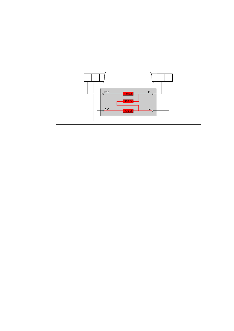
2. A terminating resistor between P+ and N- at both bus ends
(refer to Fig. 3-48)
Control terminals
RS485 terminator
29
P+
30
N-
1
+10 V
2
0 V
to terminal 2 of the next slave
Fig. 3-48
Connecting the RS485 terminator
If the frequency inverter is the last slave on the bus (refer to Fig. 3-47), then the P+
and N- of the RS485 terminator provided must be connected there to the RS485
terminals (refer to Fig. 3-48). P10 and 0 V can be connected to terminals 1 and 2
for the power supply.
If the frequency inverter is the first slave, then the bus should only be terminated
there with P+ and N- (120
Ω).
If the first or last bus node is not a MICROMASTER 4, then the bus between P+
and N– must be terminated with a resistor (between 120 Ω and 220 Ω).
The bus must be operated with a bias on one or on both ends (pull-up resistance
from P+ to P5 or P10, pull-down resistance from N– to 0 V). If the first or last bus
node is not a MICROMASTER 4 (e.g. a controller of the S7-200 series), the bus
can then be biased by connecting 390 Ω resistors from P+ to P5 and from N– to 0
V.
If the first or last bus node is a controller of the S7-200 series, SIMATIC
PROFIBUS connectors, e.g. 6ES7972-0BA41-0XA0, can be used for the bias and
the termination.