1 closed-loop pid control – Watson-Marlow MM440 User Manual
Page 175
Issue 10/06
3 Functions
MICROMASTER 440 Operating Instructions
6SE6400-5AW00-0BP0
175
3.11.1
Closed-loop PID control
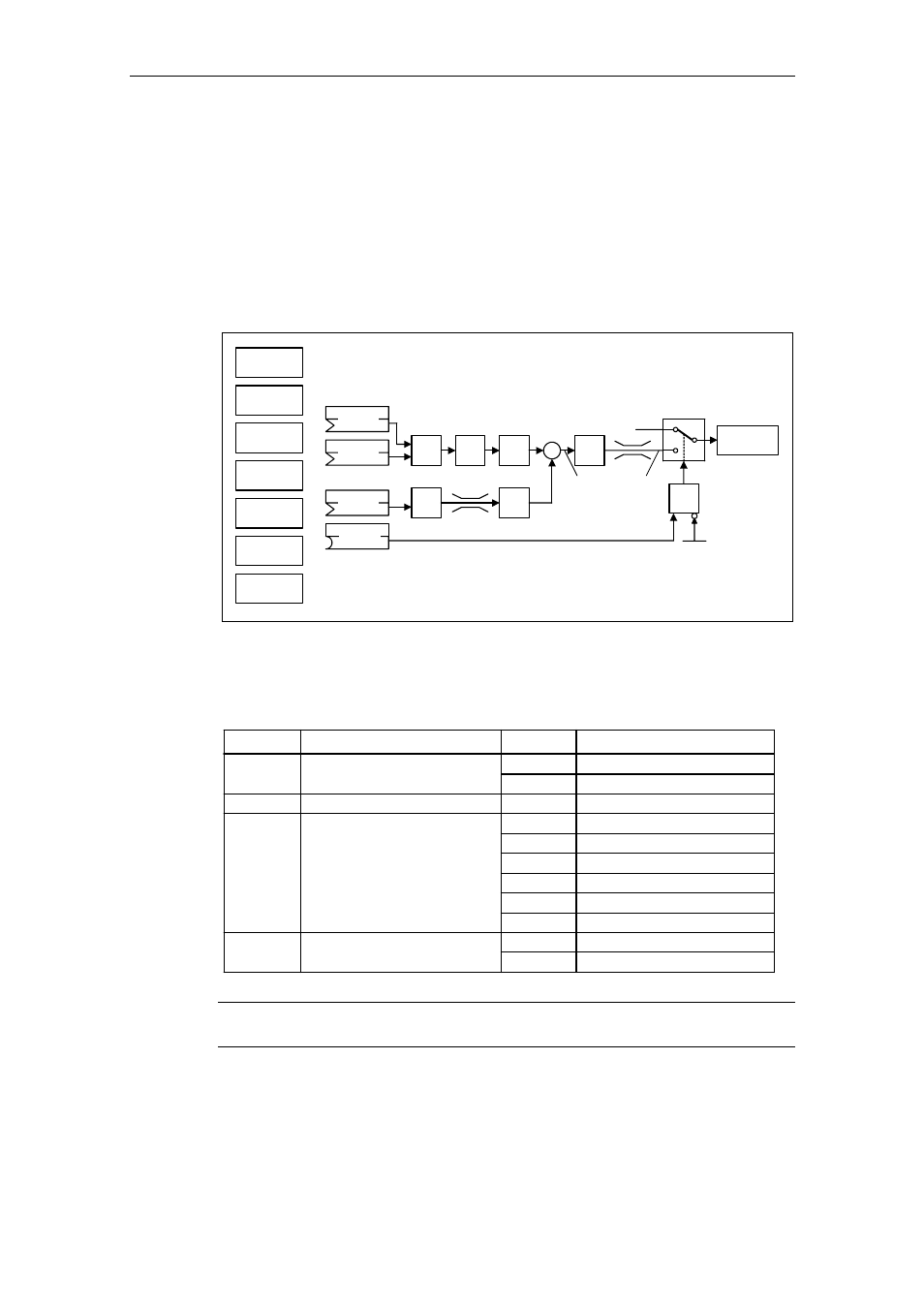
MICROMASTER has a technology controller (PID controller, enabled using
P2200); this can be used to execute basic, higher-level control functions.
The technological setpoints and actual values can be entered via the PID
motorized potentiometer (PID-MOP), PID fixed setpoint (PID-FF), analog inputs
(ADC, ADC2) or via serial interfaces (USS on BOP link, USS on COM link, CB on
COM link) (refer to the example). The appropriate parameterization of the BICO
parameter defines which setpoints or actual values are to be used (refer to Fig.
3-54).
PID
MOP
ADC
PID
SUM
PID
PID
FF
USS
BOP link
USS
COM link
CB
COM link
ADC2
P2254
P2253
PID
RFG
PID
PT1
− ∆
PID
P2200
P2264
PID
PT1
PID
SCL
&
P2251
Output
PID
0
1
Motor
control
Fig. 3-54
Structure of the technological controller (PID controller)
Important parameter settings for the setpoint and actual value sources of the
closed-loop PID control:
Parameter
BI: Enable PID controller
P2200
Parameter text
Setting
Meaning
1.0
PID controller always active
Digital input x
722.x
CI: PID setpoint
P2253
Analog input 1
755.0
USS on BOP link
2015.1
USS on COM link
2019.1
CB on COM link
2050.1
CI: PID feedback
P2264
755.0
Analog input 1
Analog input 2
755.1
PID mode
P2251
0
PID as setpoint
2224
Fixed PID setpoint (PID-FF)
PID-MOP
2250
NOTICE
Changes in parameter P2200 take effect only after a fresh ON command.