3 data sets – Watson-Marlow MM440 User Manual
Page 63
Issue 10/06
3 Functions
MICROMASTER 440 Operating Instructions
6SE6400-5AW00-0BP0
63
3.1.3 Data
sets
For many applications it is advantageous if several parameters can be
simultaneously changed, during operation or in the ready state, using an external
signal.
Examples:
¾
The drive inverter should be switched-over from motor 1 to motor 2.
MM4
M1
K1
M2
K2
Motor 1
Motor 2
Fig. 3-7
Example: Changeover from motor 1 to motor 2
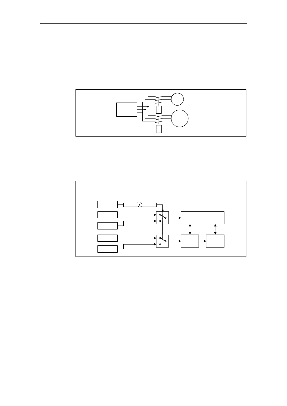
¾
The control source (e.g. terminal
→ BOP) or setpoint (frequency) source (e.g.
ADC
→ MOP) should be changed-over using a terminal signal (e.g. DIN4) as
function of an external event (e.g. the higher-level control unit fails). A typical
example in this case is a mixer, which may not come to an uncontrolled stop
when the control fails.
Control source:
Terminal
→ BOP
Setpoint (frequency source):
ADC
→ MOP
DIN4
Terminals
Sequence control
BOP
P0700[0] = 2
P0700[1] = 1
P0810 = 722.3
ADC
Setpoint
channel
MOP
0
1
P1000[0] = 2
P1000[1] = 1
Motor
control
0
1
Fig. 3-8
Example: Changing-over between the control and setpoint (frequency)
source
This functionality can be elegantly implemented using indexed parameters (refer to
Section 3.1.1). In this case, as far as the functionality is concerned, the parameters
are combined to form groups / data sets and are indexed. By using indexing,
several different settings can be saved for each parameter which can be activated
by changing-over the data set (i.e. toggling between data sets).
The following data sets apply:
CDS Command
Data
Set
DDS
Drive Data Set