Watson-Marlow MM440 User Manual
Page 141
Issue 10/06
3 Functions
MICROMASTER 440 Operating Instructions
6SE6400-5AW00-0BP0
141
Voltage input
A
D
KL1 10 V
KL2 0 V
KL4 ADC
−
KL3 ADC+
> 4.7 k
Ω
Current input
A
D
KL1 10 V
KL2 0 V
KL4 ADC
−
KL3 ADC+
A
D
KL11 ADC
−
KL10 ADC+
A
D
KL11 ADC
−
KL10 ADC+
0 ...20 mA
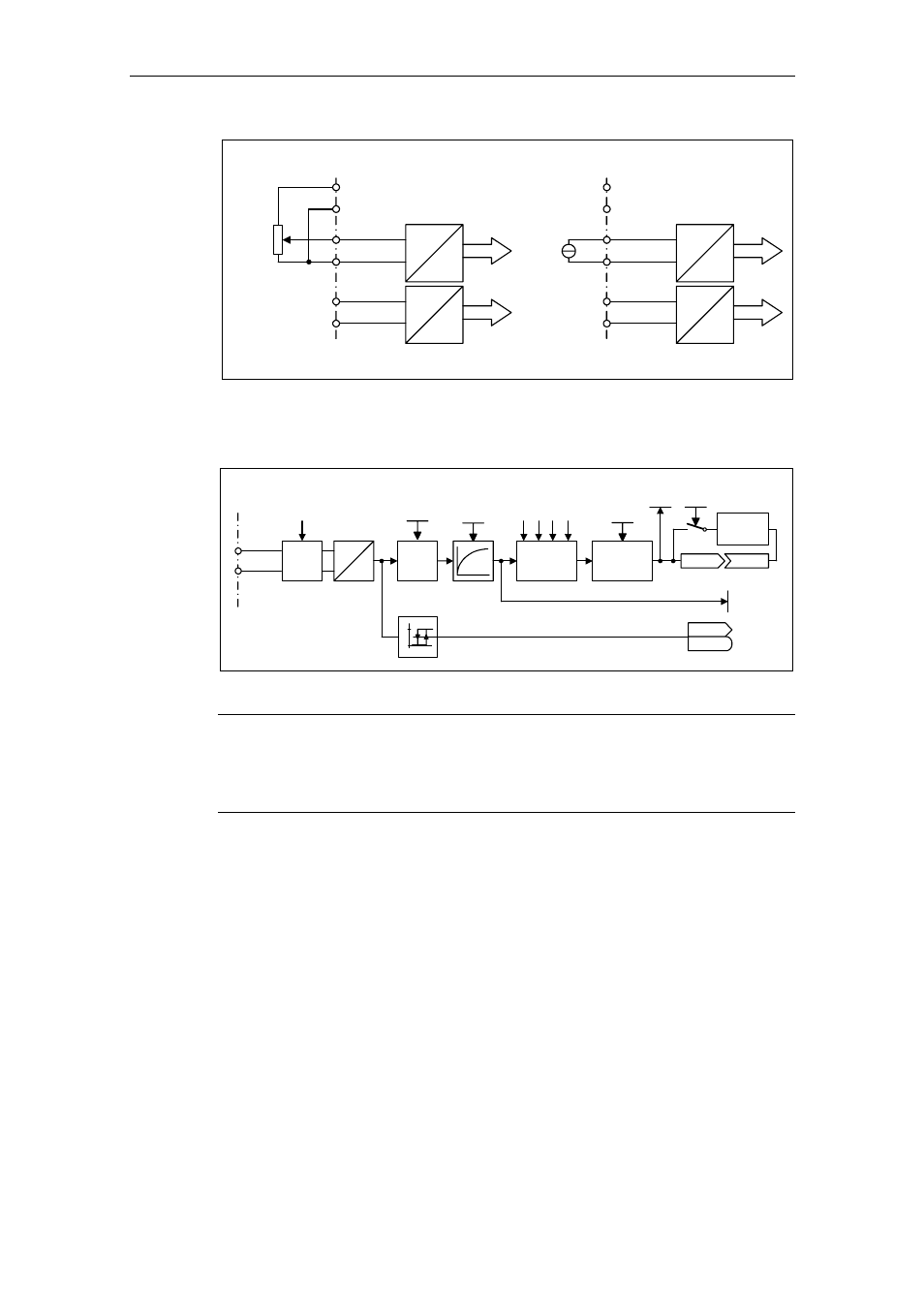
Fig. 3-32
Connection example for ADC voltage / current input
The ADC channel has several function units (filter, scaling, dead zone) (refer to
Fig. 3-33).
KL
KL
DIP switch
A
D
ADC
type
ADC
scaling
P075
7
P075
8
P075
9
P076
0
ADC
dead zone
r0755
Pxxxx
r0752
Function
P1000
ADC?
ADC+
r0754
r0722
r0722.x
P0761
P0753
P0756
0
1
ADC
type
Fig. 3-33
ADC channel
NOTE
When the filter time constant P0753 (ADC-PT1) is increased, this smooths the
ADC input signal therefore reducing the ripple. When this function is used within a
control loop, this smoothing has a negative impact on the control behavior and
immunity to noise (the dynamic performance deteriorates).