Bus structure – Watson-Marlow MM440 User Manual
Page 152
3 Functions
Issue 10/06
MICROMASTER 440 Operating Instructions
152
6SE6400-5AW00-0BP0
Table 3-15
Minimum start intervals for various baud rates
Baud rate in bit/s
Start interval in ms
2400 9,20
ms
4800 4,60
ms
9600 2,30
ms
19200 1,15
ms
38400 0,57
ms
57600 0,38
ms
76800 0,29
ms
93750 0,24
ms
115200 0,19
ms
Only an STX with a preceding start interval identifies the valid start of a telegram.
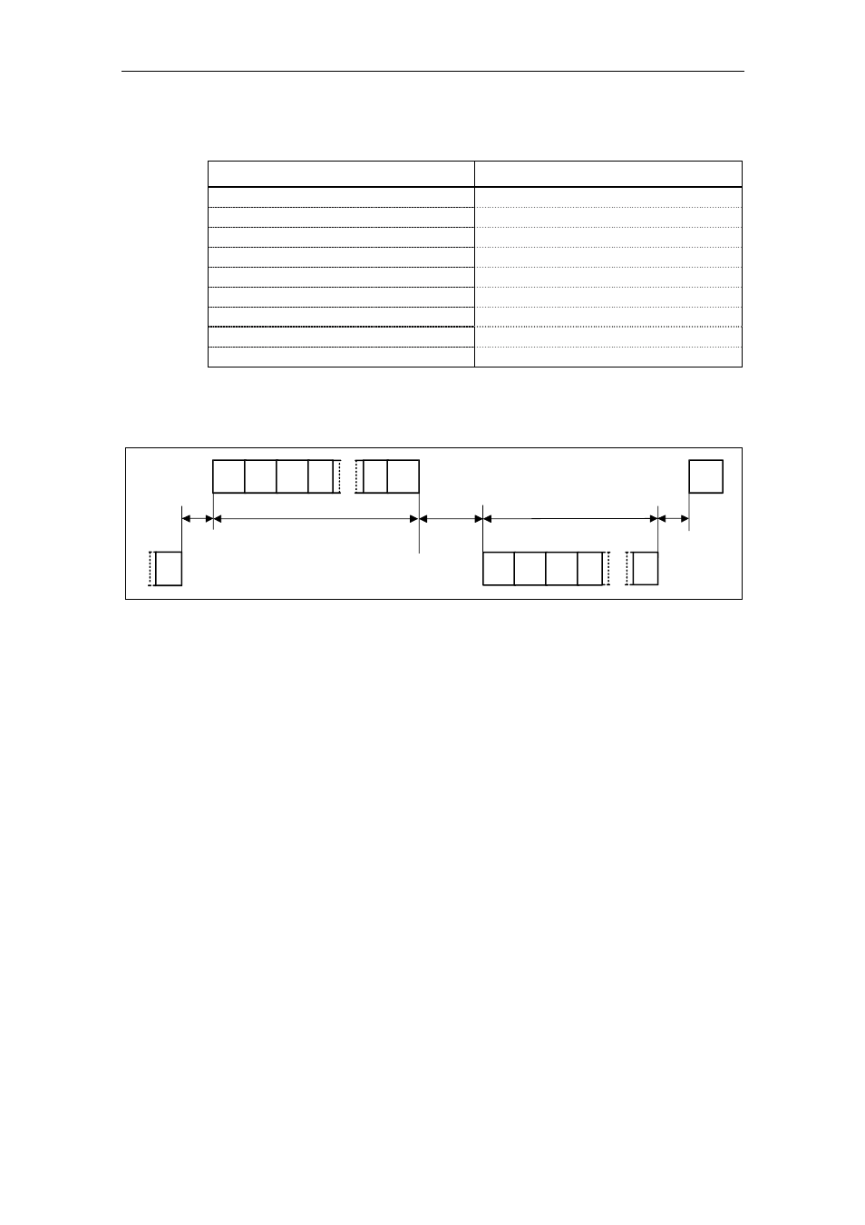
Data is always transferred in accordance with the diagram illustrated below (half-
duplex mode):
Master transmits
Start
pause
STX LGE ADR 1.
n BCC
STX LGE ADR 1.
BCC
BCC
STX
Slave transmits
Reply delay
time
Start
pause
Fig. 3-43
Transmit sequence
The time interval between the last character of the task telegram (BCC) and the
start of the reply telegram (STX) is known as the reply delay time. The maximum
permissible reply delay time is 20 ms, but it must not be less than the start interval.
If node x does not respond within the maximum permissible reply delay time, an
error message is deposited in the master.
The master than sends the telegram for the next slave node.
Bus structure
The data transfer medium and the physical bus interface are essentially
determined by what the bus system is used for. The physical interface of the USS
protocol is based on the "Recommended Standard RS-485". For point-to-point
links, a sub-quantity of EIA RS-232 (CCITT V.24) or TTY (20 mA current loop) can
be used as the physical interface.
The USS bus is based on a linear topology without branches. Both ends of the line
terminate at a node. The maximum cable length (50 m) and therefore the maximum
distance between the master and the last slave is limited by the characteristics of
the cable, the ambient conditions and the data transfer rate [EIA Standard RS-422-
A Dezember 1978, Appendix, Page 14]
The number of nodes is limited to a maximum of 33 (1 master, 32 slaves).