Watson-Marlow MM440 User Manual
Page 231
Issue 10/06
3 Functions
MICROMASTER 440 Operating Instructions
6SE6400-5AW00-0BP0
231
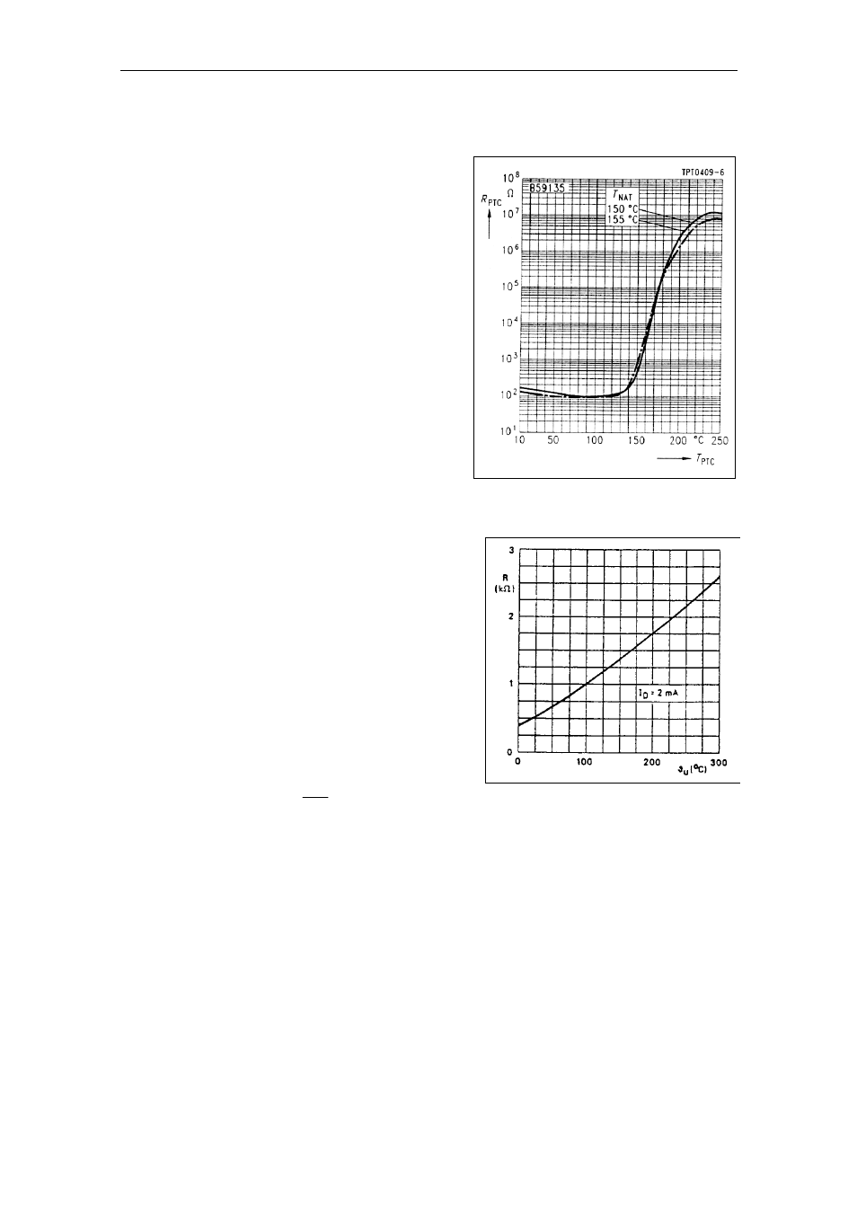
With PTC temperature sensor (P0601 = 1)
The PTC is connected to the control
terminals 14 and 15 of the
MICROMASTER 440. PTC monitoring
is activated with the parameter setting
P0601 = 1. If the resistance value,
connected at the terminals, is less than
1500
Ω, then neither alarm nor fault is
generated. If this value is exceeded, the
drive inverter outputs alarm A0511 and
fault F0011. The resistance value where
the alarm and fault are output does not
lie below 1000
Ω and not above
2000
Ω.
Response thresholds: 4.0 V 0
→ 1
3.8 V 1
→ 0
With KTY84 temperature sensor (P0601 = 2)
The KTY84 must be connected so that the
diode is in the conductive direction. This
means that the anode is connected to
terminal 14 and the cathode to terminal 15.
If the temperature monitoring function is
activated with the setting P0601 = 2, the
temperature of the sensor (i.e. of the motor
windings) is written into parameter r0035
(refer toFig. 3-93). The threshold
temperature
ϑ
trip
(refer to Table 3-36) of the
motor can now be set using the warning
threshold, motor overtemperature
ϑ
warn
(parameter P0604) (the factory setting is
130 °C). The following applies:
1
.
1
P0604
trip
warn
ϑ
=
ϑ
=
Wire breakage or short-circuit
If the circuit between the drive inverter and PTC or KTY84 sensor is interrupted or
there is a short-circuit, the drive inverter is shut down (tripped) and fault F0015 is
displayed.
Fig. 3-95
PTC characteristic for
1LG / 1LA motors
Fig. 3-96
KTY84 characteristic for
1LG / 1LA motors