2 kinetic buffering (vdc_min controller) – Watson-Marlow MM440 User Manual
Page 218

3 Functions
Issue 10/06
MICROMASTER 440 Operating Instructions
218
6SE6400-5AW00-0BP0
3.18.2 Kinetic
buffering
(Vdc_min controller)
Parameter range:
P1240
r0056 bit 15
P1245, r1246, P1247
P1250 – P1253
P1256,
P1257
Warnings A0503
Faults F0003
Function chart number:
FP4600
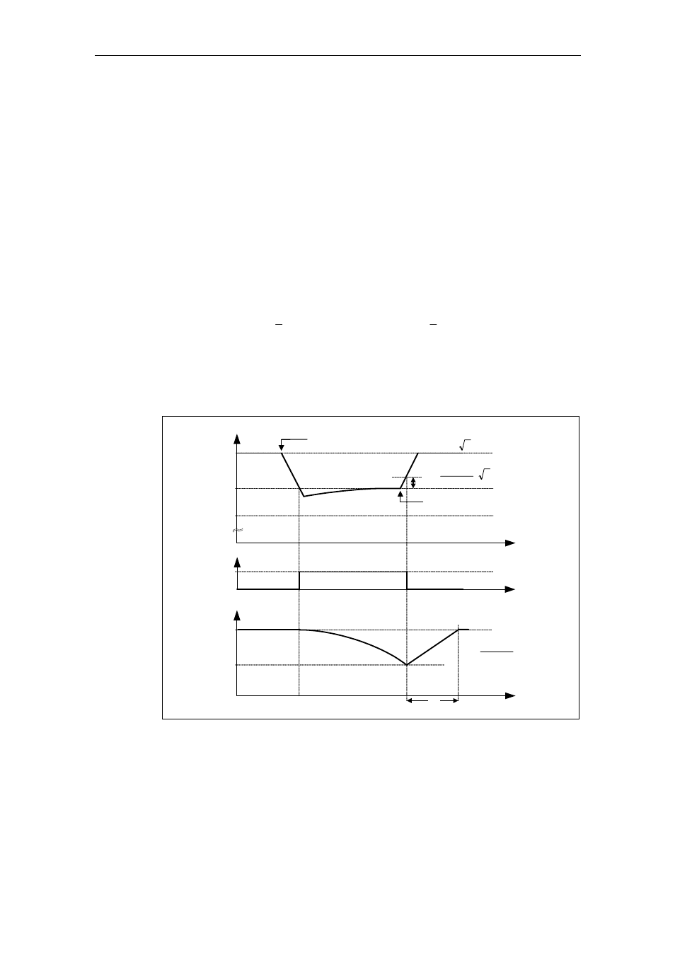
Brief line supply failures can be buffered using the kinetic buffering function
(enabled using P1240). Line supply failures are buffered using the kinetic energy
(i.e. moments of inertia) of the driven load. In this case the prerequisite is that the
driven load has a sufficiently high flywheel mass or is rotating at an appropriately
high speed – i.e. has adequate kinetic or rotating energy.
2
kin
mv
2
1
W
:
Energie
Kinetische
=
2
rot
J
2
1
W
:
nergie
Rotationse
ω
=
Using this technique, the frequency is controlled (closed-loop), so that energy is fed
to the drive inverter from the regenerating motor thus covering the system losses.
The losses during the line supply failure still remain which means that the motor
speed decreases. When using kinetic buffering it has to be taken into consideration
that the motor speed reduces.
t
1
KIB active
t
V
DC
100 %
0
r0056
Bit 15
P1245
5 %
Power restoration
Power failure
V
dc_min
0210
P
2
100
P1245
⋅
⋅
0210
P
2
⋅
I
f
I
f
1
f
2
P1120
P1082
f
-
f
t
2
1
b
⋅
=
t
t
b
Fig. 3-84
Kinetic buffering (Vdc_min controller)
When the line supply returns, the energy feed is again from the line side and the
output frequency of the drive inverter returns to the selected setpoint along the
ramp defined by the ramp-function generator.