Watson-Marlow MM440 User Manual
Page 174
3 Functions
Issue 10/06
MICROMASTER 440 Operating Instructions
174
6SE6400-5AW00-0BP0
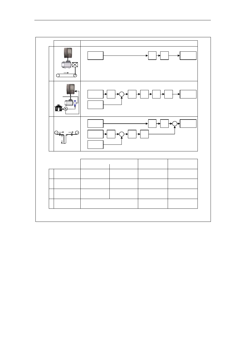
Application
Control structure
SUM
setpoint
PID
RFG
PID
AFM
RFG
x
2
v
2
v
1
4
2
PID
setpoint
PID
feedback
PID
RFG
PID
PID
limit
AFM
RFG
v
2
*
x
2
*
x
2
p
2
*
p
2
P2200 = 0:0
2)
P2251 = 0
1
P2200 = 1:0
2)
P2251 = 0
2
P2200 = 0:0
1)
P2251 = 1
3
P2200 = 1:0
1)
P2251 = 1
4
−
−
−
ON: active
OFF1/3: active
ON: -
OFF1/3: -
ON: -
OFF1/3: -
SUM
PID controller
RFG
PID-RFG
1) will take change with drive running
2) change only taken when drive stopped
−
−
VSD
Dancer control
ON: active
OFF1/3: active
ON: active
OFF1/3: active
ON: active
OFF1/3: active
ON: active
OFF1/3: -
ON: -
OFF1/3: active
PID
setpoint
PID
feedback
PID
limit
Motor
control
Motor
control
Setpoint via
PID control
VSD
PID control
Dancer control
Variable speed drive (VSD)
1
3
p
2
SUM
setpoint
AFM
RFG
Motor
control
v
Fig. 3-53
Structure of the technology controller