Watson-Marlow MM440 User Manual
Page 216
3 Functions
Issue 10/06
MICROMASTER 440 Operating Instructions
216
6SE6400-5AW00-0BP0
t
t
⏐f⏐
1
-controller active
V
DC_max
t
V
DC
r1242
0
r0056 Bit 14
f
f
act
set
A0911
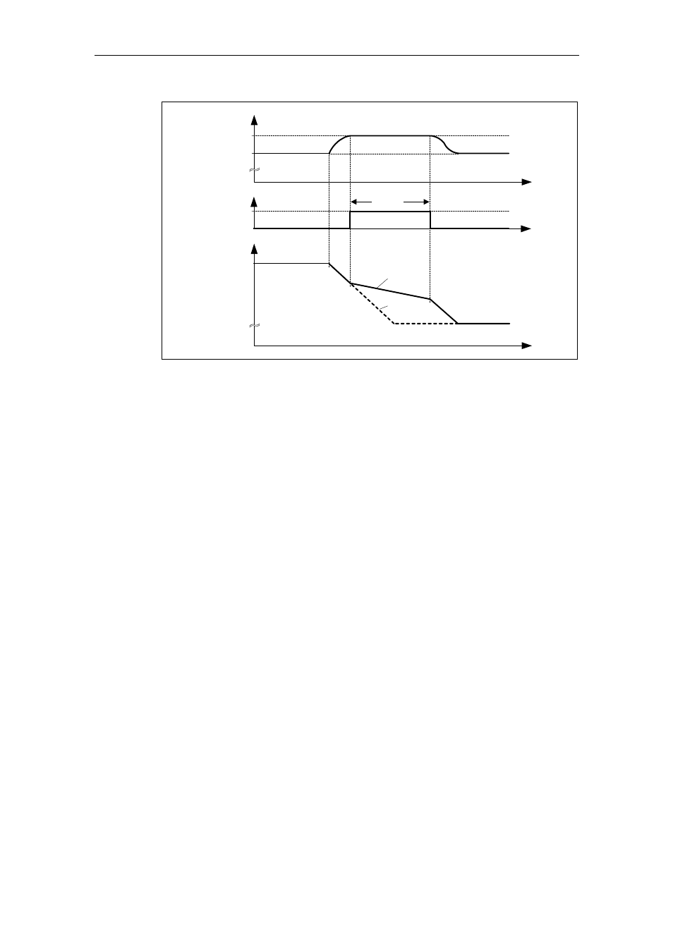
Fig. 3-83
Vdc_max controller
On the other hand, if the Vdc_max controller increases the output frequency (e.g.
for a steady-state regenerative load), then the Vdc_max controller is disabled by an
internal drive inverter monitoring function and warning A0910 is output. If the
regenerative load continues, the drive inverter is protected using fault F0002.
In addition to controlling the DC link (closed-loop), the Vdc_max controller supports
the stabilizing processes of the speed at the end of an acceleration phase. This is
especially the case if there is an overshoot and the motor therefore briefly goes into
regenerative operation (damping effect).
The automatic increase of the braking ramp (refer to Fig. 3-83) can be
contradictory to the objective of the application. This behavior is not required,
especially for positioning drives and hoisting gear (e.g. cranes). A DC link
overvoltage condition can still be avoided by disabling the Vdc-max controller
(P1240 = 0) and by activating the following functions:
¾
Extending the braking ramp (P1121)
¾
Activating the compound brake (P1236) or dynamic brake (P1230)