3 pid dancer roll control, The velocity v, Should be controlled using drive rolls a – Watson-Marlow MM440 User Manual
Page 179: So that the length x
Issue 10/06
3 Functions
MICROMASTER 440 Operating Instructions
6SE6400-5AW00-0BP0
179
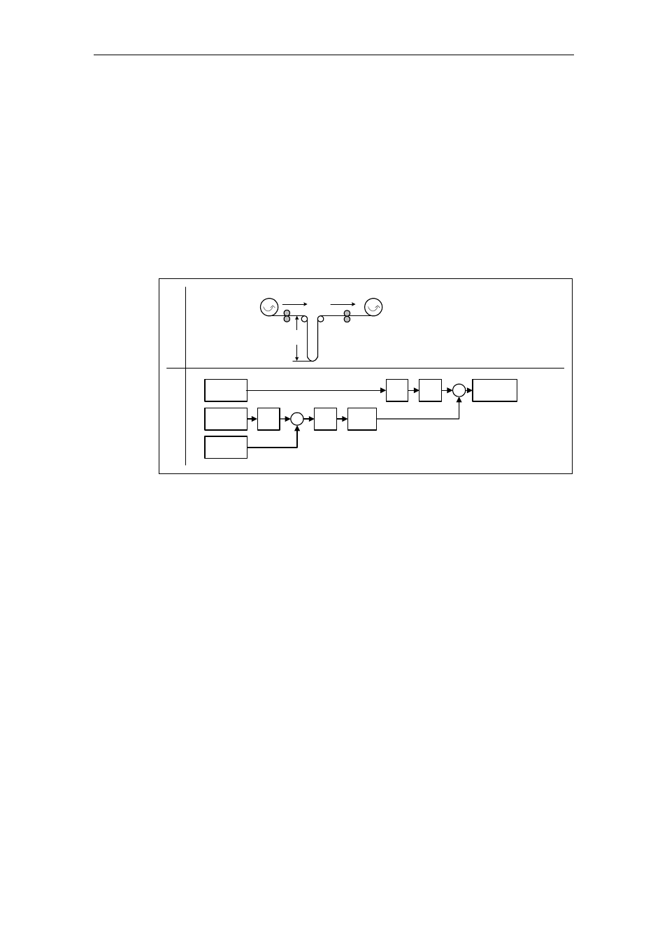
3.11.1.3 PID dancer roll control
For various continuous production processes, e.g. in the paper and pulp industry,
or in the manufacture of cables, it is necessary to control (closed-loop) the velocity
of stations along the production process so that the continuous material web is not
subject to any inadmissible tension levels. It is also important that no folds or
creases are formed. For applications such as these, it is practical to provide a type
of material buffer in the form of a loop with a defined tension. This provides a de-
coupling between the individual drive locations. This loop represents the difference
between the material fed-in and that fed-out and therefore indicates the process
quality.
Using the PID dancer roll control, with MICROMASTER 440 it is possible to ensure
that continuous material webs have a constant tension.
SUM
setpoint
PID
RFG
PID
AFM
RFG
x
2
v
2
v
1
v
2
*
x
2
*
x
2
−
PID
setpoint
PID
feedback
PID
limit
Motor
control
S
tru
ct
ure
A
pp
lic
at
io
n
Fig. 3-57
PID dancer roll control
The velocity v
1
is assumed to be an independent disturbance; the input velocity v
2
should be controlled using drive rolls A
2
so that the length x
2
of the loop
corresponds, as far as possible, to the setpoint.
The structure and important parameters for the PID dancer roll control are listed in
Fig. 3-58 and Table 3-27.