3 fault detection, Fault displays, causes, and possible solutions, Fault detection – Yaskawa D1000 Series Power Regenerative Converter User Manual
Page 109

5.3 Fault Detection
YASKAWA ELECTRIC TOEP C710656 07C YASKAWA Power Regenerative Converter - D1000 Instruction Manual
109
Tr
ou
blesh
oot
ing
5
5.3 Fault Detection
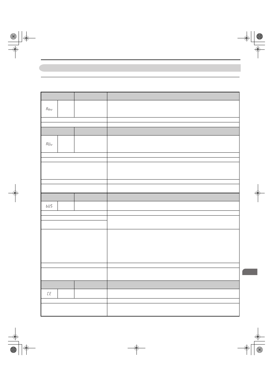
◆ Fault Displays, Causes, and Possible Solutions
Table 5.6 Detailed Fault Displays, Causes, and Possible Solutions
Digital Operator
Display
Fault Name
Details
Aov
Power Supply
Overvoltage
The input power supply voltage became equal to or higher than the Input Power Supply
Overvoltage Detection Level (L8-36).
200 V Class: Approximately 277 Vac
400 V Class: Approximately 554 Vac
Cause
Possible Solution
The input power supply voltage is too high.
Reduce the voltage to within the range in the power supply specifications.
Digital Operator
Display
Fault Name
Details
AUv
Power Supply
Undervoltage
The input power supply voltage became equal to or lower than the Input Power Supply
Undervoltage Detection Level.
200 V Class: Approximately 150 Vac
400 V Class: Approximately 300 Vac
Cause
Possible Solution
The capacity of the power supply is too small.
Increase the capacity of the power supply.
The AC fuse is open.
A transistor inside the converter was destroyed.
The input wiring is ground-faulted or short-circuited.
Or, the drive output is ground-faulted or short-circuited, which destroyed the output transistor.
Consult with your Yaskawa representative or the nearest Yaskawa sales office.
The distortion in the power supply is too large. Lower the impedance of the input power supply wiring.
A phase loss occurred in the input power
supply.
Check the input power supply for phase loss or an imbalance in the interphase voltages.
Investigate and correct the cause and reset the fault.
Digital Operator
Display
Fault Name
Details
bUS
Option Communication
Error
• The connection was lost after establishing initial communication.
• Only detected when the run command frequency reference is assigned to an option card.
Cause
Possible Solution
No signal was received from the PLC.
Check for faulty wiring.
• Correct the wiring.
• Check for disconnected cables and short circuits and repair as needed.
Faulty communications wiring or an existing
short circuit.
Communication data error occurred due to
noise.
Check the various options available to minimize the effects of noise.
• Counteract noise in the control circuit, main circuit, and ground wiring.
• Ensure that other equipment such as switches or relays do not cause noise. Use surge absorbers
if necessary.
• Use only recommended cables or other shielded line. Ground the shield on the controller side
or the converter input power side.
• Separate all communication wiring from drive power lines. Install an EMC noise filter to the
converter power supply input.
The option card is damaged.
Replace the option card if there are no problems with the wiring and the error continues to occur.
The option card is not properly connected to
the converter.
The connector pins on the option card do not line up properly with the connector pins on the
converter.
Reinstall the option card.
Digital Operator
Display
Fault Name
Details
CE
MEMOBUS/Modbus
Communication Error
Control data was not received for the CE detection time set to H5-09.
Cause
Possible Solution
Faulty communications wiring or an existing
short circuit.
Check for faulty wiring.
• Correct the wiring.
• Check for disconnected cables and short circuits and repair as needed.
TOEP_C710656_07C_2_0.book 109 ページ 2015年1月9日 金曜日 午後6時23分