Writing to multiple registers – Yaskawa D1000 Series Power Regenerative Converter User Manual
Page 218
C.8 Message Examples
218
YASKAWA ELECTRIC TOEP C710656 07C YASKAWA Power Regenerative Converter - D1000 Instruction Manual
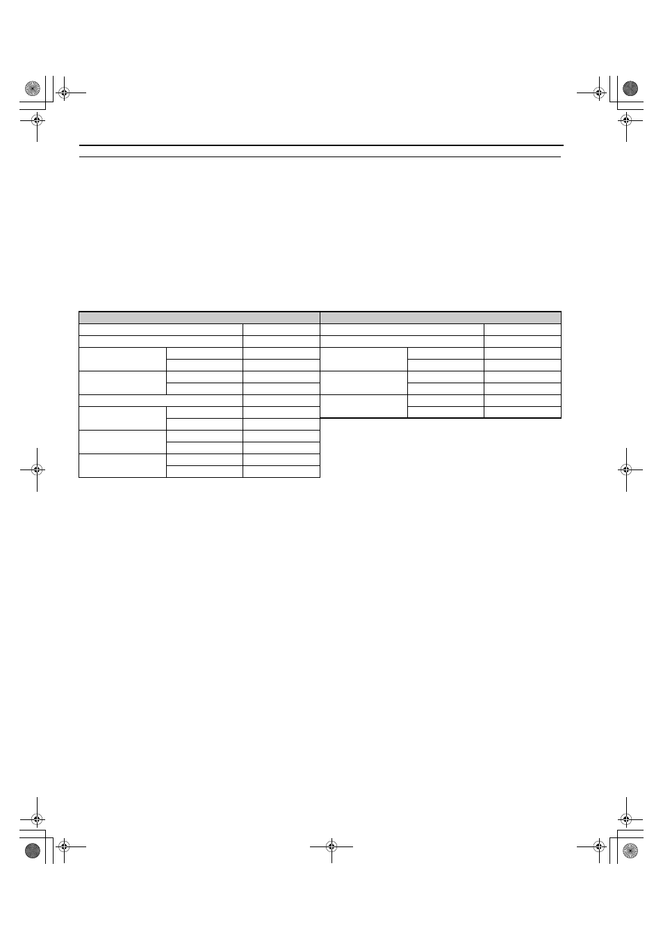
◆ Writing to Multiple Registers
Function code 10H allows the user to write multiple converter MEMOBUS/Modbus registers with one message. This
process works similar to reading registers, in that the address of the first register to be written and the data quantity are set
in the command message. The data to be written must be consecutive so that the register addresses are in order, starting
from the specified address in the command message. The data order must be high byte then lower byte.
The following table shows an example of a message where 2000H has been set with a Multi-Function Analog Output 1
and 4000H has been set with a Multi-Function Analog Output 2 for the slave 1 converter.
If parameter values are changed using the Write command, an Enter command may be necessary to activate or save the
data depending on the setting of H5-11. Refer to
H5-11: Communications Enter Function Selection on page 212
Refer to
for detailed descriptions.
Note: Double the number of the data quantity for the number of bytes in the command message.
Command Message
Response Message (normal)
Slave Address
01H
Slave Address
01H
Function Code
10H
Function Code
10H
Starting No.
Upper
00H
Starting No.
Upper
00H
Lower
07H
Lower
07H
Data Quantity
Upper
00H
Data Quantity
Upper
00H
Lower
02H
Lower
02H
Number of Bytes
04H
CRC-16
Upper
F0H
Starting Data
Upper
20H
Lower
09H
Lower
00H
Next Data
Upper
40H
Lower
00H
CRC-16
Upper
88H
Lower
49H
TOEP_C710656_07C_2_0.book 218 ページ 2015年1月9日 金曜日 午後6時23分