Menu structure for digital operator, 2 using the digital operator, Initial display – Yaskawa D1000 Series Power Regenerative Converter User Manual
Page 89
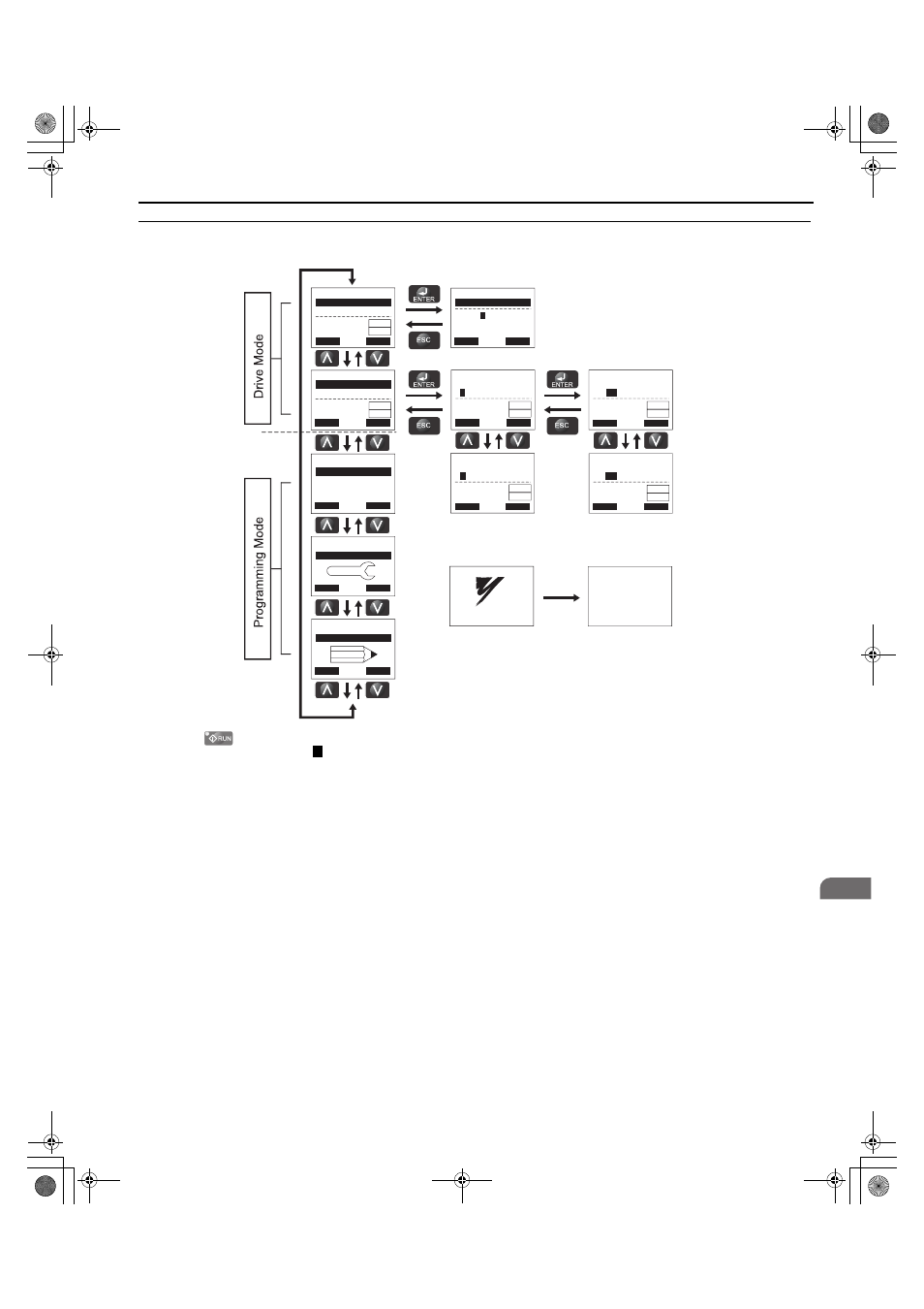
4.2 Using the Digital Operator
YASKAWA ELECTRIC TOEP C710656 07C YASKAWA Power Regenerative Converter - D1000 Instruction Manual
89
S
ta
rt
-Up Pr
ogr
amming
&
O
p
er
at
io
n
4
◆ Menu Structure for Digital Operator
Figure 4.2 Digital Operator Menu and Screen Structure
<1> Pressing
will start the converter operation.
<2> Flashing characters are shown as .
<3> “X” characters are used as examples in this manual. The LCD Operator will display the actual setting values.
<4> The DC Bus Voltage Reference appears after the initial display that shows the product name.
<5> The information that appears on the display will vary depending on the converter.
- MODE -
U1-51= 330V
U1-52= 330V
U1-53= 0.00A
DRV
Volt Ref (OPR)
Rdy
-MONITR-
Volt Ref (d8-01)
U1-51=
0
330V
<2>
<3>
<1>
(300 ~ 360)
“330V”
DRV
←
→
Rdy
- MODE -
U1-51= 330V
U1-52= 330V
U1-53= 0.00A
DRV
Monitor Menu
Rdy
- MODE -
PRG
Modified Consts
HELP
HELP
DATA
- MODE -
PRG
Quick Setting
DATA
HELP
- MODE -
PRG
DATA
Programming
-MONITR-
U
1
-51= 330V
U1-52= 330V
U1-53= 0.00A
DRV
Monitor
Rdy
-MONITR-
U1-
51
= 330V
U1-52= 330V
U1-53= 0.00A
DRV
DC V Command
Rdy
-MONITR-
U1-
52
= 330V
U1-53= 0.00A
U1-54= 200V
DRV
DC V Feedback
Rdy
-MONITR-
U
2
-01= oC
U2-02= oPr
U2-11= 00000000
DRV
Fault Trace
Rdy
Modified
X Parameters
RSEQ
LREF
RSEQ
LREF
RSEQ
LREF
RSEQ
LREF
RSEQ
LREF
RSEQ
LREF
YASKAWA
D1000
XXXV, X.XkW
XX.XXA
<XXXXXXXXX>
Initial Display
<4>
<5>
0
TOEP_C710656_07C_2_0.book 89 ページ 2015年1月9日 金曜日 午後6時23分