Yaskawa D1000 Series Power Regenerative Converter User Manual
Page 194
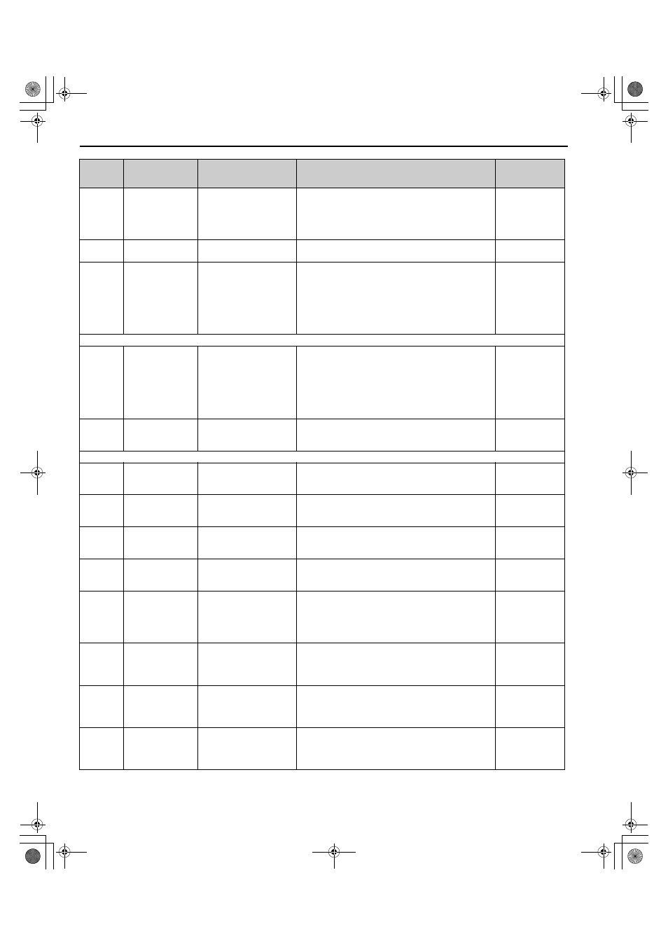
B.2 Parameter Tables
194
YASKAWA ELECTRIC TOEP C710656 07C YASKAWA Power Regenerative Converter - D1000 Instruction Manual
o2-06
(50AH)
Operation Selection
when Digital
Operator is
Disconnected
Oper Discon Det
0: Disabled
1: Enabled
Determines the operation when the digital operator is
disconnected.
0: The converter continues operating if the digital operator
is disconnected.
1: A fault is triggered (oPr) and the motor coasts to stop.
Default: 1
Min.: 0
Max.: 1
o2-09
(50DH)
Reserved
–
–
–
o2-21
(81AH)
converter Check
US signal check
0: Nomal
1: Start
Sets the operation for Converter Capacity Setting Fault
(oPE01).
Set this parameter to 1 to reset an oPE01 fault without
cycling the power supply.
0: Standard
1: Recheck converter (The parameter returns to 0 after it is
set.)
Default: 0
Min.: 0
Max.: 1
o3: Copy Function
o3-01
(515H)
Copy Function
Selection
COPY SELECT
0: COPY SELECT
1: INV
→OP READ
2: OP
→INV WRITE
3: OP
←→INV
VERIFY
0: No action
1: Read parameters from the converter, saving them onto
the digital operator.
2: Copy parameters from the digital operator, writing them
to the converter.
3: Verify parameter settings on the converter to check if
they match the data saved on the operator.
Default: 0
Min.: 0
Max.: 3
o3-02
(516H)
Copy Allowed
Selection
Read Allowable
0: Disabled
1: Enabled
0: Read operation prohibited
1: Read operation allowed
Default: 0
Min.: 0
Max.: 1
o4: Maintenance Monitor Settings
o4-01
(50BH)
Cumulative
Operation Time
Setting
DrvElapsTimeCnt
Sets the value for the cumulative operation time of the
converter in units of 10 h.
Default: 0
Min.: 0
Max.: 9999
o4-02
(50CH)
Cumulative
Operation Time
Selection
ElapsTimeCntSet
0: Power-On Time
1: Running Time
0: Logs power-on time
1: Logs operation time when the converter output is active
(output operation time).
Default: 0
Min.: 0
Max.: 1
o4-03
(50EH)
Cooling Fan
Operation Time
Setting
FanElapsTimeCn
Sets the value of the fan operation time monitor U4-03 in
units of 10 h.
Default: 0
Min.: 0
Max.: 9999
o4-05
(51DH)
Capacitor
Maintenance Setting
BusCap Maint Set
Sets the value of the Maintenance Monitor for the
capacitors. See U4-05 to check when the capacitors may
need to be replaced.
Default: 0%
Min.: 0%
Max.: 150%
o4-07
(523H)
DC Bus Pre-Charge
Relay Maintenance
Setting DC Bus
Pre-Charge Relay
Maintenance Setting
ChrgCircMaintSet
Sets the value of the Maintenance Monitor for the soft
charge bypass relay.
See U4-06 to check when the bypass relay may need to be
replaced.
Default: 0%
Min.: 0%
Max.: 150%
o4-11
(510H)
U2, U3 Initialization
Fault Data Init
0: No Reset
1: Reset
0: U2- and U3- monitor data is not reset when the
converter is initialized (A1-03).
1: U2- and U3- monitor data is reset when the
converter is initialized (A1-03).
Default: 0
Min.: 0
Max.: 1
o4-12
(512H)
kWh Monitor
Initialization
kWh Monitor Init
0: No Reset
1: Reset
0: U4-10 and U4-11 monitor data is not reset when the
converter is initialized (A1-03).
1: U4-10 and U4-11 monitor data is reset when the
converter is initialized (A1-03).
Default: 0
Min.: 0
Max.: 1
o4-13
(528H)
Number of Run
Commands Counter
Initialization
Run Counter Init
0: No Reset
1: Reset
0: Number of Run commands counter is not reset when the
converter is initialized (A1-03).
1: Number of Run commands counter is reset when the
converter is initialized (A1-03).
Default: 0
Min.: 0
Max.: 1
No.
(Address
Hex)
Name
LCD Display
Description
Values
TOEP_C710656_07C_2_0.book 194 ページ 2015年1月9日 金曜日 午後6時23分