Yaskawa D1000 Series Power Regenerative Converter User Manual
Page 121
5.4 Alarm Detection
YASKAWA ELECTRIC TOEP C710656 07C YASKAWA Power Regenerative Converter - D1000 Instruction Manual
121
Tr
ou
blesh
oot
ing
5
Digital Operator
Display
Minor Fault Name
Detail
Alarm
Output
(H2-=10)
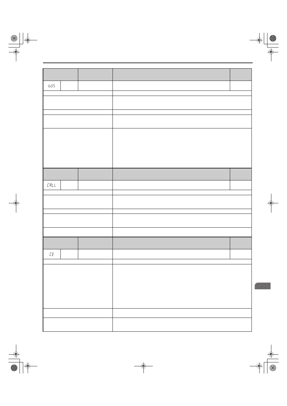
bUS
Option Communication
Error
• The connection was lost after initial communication was established.
• Assign a Run command frequency reference to the option.
YES
Cause
Possible Solutions
Connection is broken or master controller
stopped communicating.
• Check for faulty wiring.
• Correct the wiring.
• Check for disconnected cables and short circuits. Repair as needed.
Option is damaged.
If there are no problems with the wiring and the fault continues to occur, replace the option.
The option is not properly connected to the
converter.
• The connector pins on the option are not properly lined up with the connector pins on the
converter.
• Reinstall the option.
A data error occurred due to noise.
• Check options available to minimize the effects of noise.
• Take steps to counteract noise in the control circuit wiring, main circuit lines and ground
wiring.
• Try to reduce noise on the controller side.
• Use surge absorbers on magnetic contactors or other equipment causing the disturbance.
• Use recommended cables or some other type of shielded line. Ground the shield to the
controller side or on the input power side.
• Separate the wiring for communication devices from the converter input power lines. Install an
EMC noise filter to the converter input power.
Digital Operator
Display
Minor Fault Name
Detail
Alarm
Output
(H2-=10)
CALL
Serial Communication
Transmission Error
Communication has not yet been established.
YES
Cause
Possible Solutions
Communications wiring is faulty, there is a
short circuit, or something is not connected
properly.
• Check for wiring errors.
• Correct the wiring.
• Check for disconnected cables and short circuits. Repair as needed.
Programming error on the master side.
Check communications at start-up and correct programming errors.
Communications circuitry is damaged.
• Perform a self-diagnostics check.
• If the problem continues, replace either the control board or the entire converter. For
instructions on replacing the control board, contact Yaskawa or your nearest sales representative.
Termination resistor setting is incorrect.
Install a termination resistor at both ends of a communication line. Set the internal termination
resistor switch correctly on slave converters. Place DIP switch S2 to the ON position.
Digital Operator
Display
Minor Fault Name
Detail
Alarm
Output
(H2-=10)
CE
MEMOBUS/Modbus
Communication Error
Control data was not received correctly for two seconds.
YES
Cause
Possible Solutions
A data error occurred due to noise.
• Check options available to minimize the effects of noise.
• Take steps to counteract noise in the control circuit wiring, main circuit lines, and ground
wiring.
• Reduce noise on the controller side.
• Use surge absorbers for the magnetic contactors or other components that may be causing the
disturbance.
• Use only recommended shielded line. Ground the shield on the controller side or on the
converter input power side.
• Separate all wiring for communication devices from converter input power lines. Install an
EMC noise filter to the converter input power supply.
Communication protocol is incompatible.
• Check the H5 parameter settings and the protocol setting in the controller.
• Ensure settings are compatible.
The CE detection time (H5-09) is set shorter
than the time required for a communication
cycle to take place.
• Check the PLC.
• Change the software settings in the PLC.
• Set a longer CE detection time using parameter H5-09.
TOEP_C710656_07C_2_0.book 121 ページ 2015年1月9日 金曜日 午後6時23分