Yaskawa D1000 Series Power Regenerative Converter User Manual
Page 125
5.4 Alarm Detection
YASKAWA ELECTRIC TOEP C710656 07C YASKAWA Power Regenerative Converter - D1000 Instruction Manual
125
Tr
ou
blesh
oot
ing
5
The ambient temperature is too high.
Check the ambient temperature.
• Improve ventilation in the control panel.
• Install a cooling device (e.g., a cooling fan or air conditioner) and lower the ambient
temperature.
• If there are heat-generating objects nearby, remove them.
The load is too large.
Measure the output current.
Lower the load.
Internal cooling fan has stopped.
• Replace the cooling fan. Refer to page
for details.
• After replacing the converter, set parameter o4-03 to 0 to reset the cooling fan operation time.
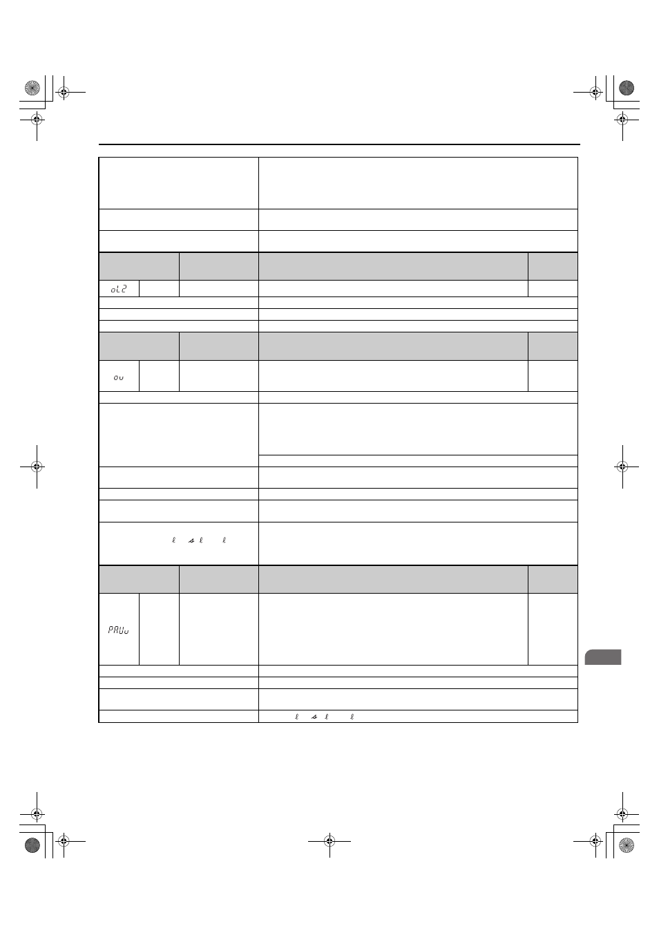
Digital Operator
Display
Minor Fault Name
Detail
Alarm
Output
(H2-=10)
oL2
Converter Overload
The thermal sensor of the converter triggered the converter overload protection.
YES
Cause
Possible Solutions
Load is too heavy.
Reduce the load.
The converter does not operate.
Start converter operation first, and then start converter operation.
Digital Operator
Display
Minor Fault Name
Detail
Alarm
Output
(H2-=10)
ov
DC Bus Overvoltage
The DC bus voltage exceeded the trip point.
• 200 V Class: Approximately 410 V
• 400 V Class: Approximately 820 V
YES
Cause
Possible Solutions
Electrical noise interference causes the
converter to operate incorrectly.
• Review possible solutions for handling noise interference.
• Review section on handling noise interference and check control circuit lines, main circuit lines
and ground wiring.
• If the magnetic contactor is identified as a source of noise, install a surge protector to the MC
coil.
Set number of fault restarts (L5-01) to a value other than 0.
There was a regenerative load while the
converter is stopped.
Operate the converter.
The power supply voltage is too high.
Lower the voltage so that it is within the power supply specifications of the converter.
There is a regenerative load while the converter
is stopped.
Operate the converter.
The wiring of the power supply voltage
detection circuits (
) and
the wiring of the main circuit terminals (R/L1,
S/L2, and T/L3) is not correct.
Check the wiring.
Correct the wiring.
Digital Operator
Display
Minor Fault Name
Detail
Alarm
Output
(H2-=10)
PAUv
Power Supply
Undervoltage
Pre-Alarm
The input power supply voltage became equal to or lower than the Input Power
Supply Undervoltage Detection Level.
200 V Class: Approximately 150 Vac
400 V Class: Approximately 300 Vac
The converter enters the baseblock state during pre-alarm. When the input supply
voltage is restored during the pre-alarm, the converter will release the base block
and continue to operate.
YES
Cause
Possible Solutions
The power supply voltage is low.
Increase the power supply voltage.
A phase loss occurred in the input power
supply.
Check the input power supply for phase loss or an imbalance in the interphase voltages.
Investigate and correct the cause and reset the fault.
Voltage detection failed.
Check r1/ 11, 1/ 21, t1/ 31 to see if they are wired correctly.
r1/ 11, 1/ 21, t1/ 31
TOEP_C710656_07C_2_0.book 125 ページ 2015年1月9日 金曜日 午後6時23分