Emc guidelines compliance, Table d.3, Grounding – Yaskawa D1000 Series Power Regenerative Converter User Manual
Page 238: Guarding against harmful materials, Emc filter installation
D.2 European Standards
238
YASKAWA ELECTRIC TOEP C710656 07C YASKAWA Power Regenerative Converter - D1000 Instruction Manual
Table D.3 Three Phase Input Reactor for Harmonics Filter
■
Grounding
The converter is designed to be used in T-N (grounded neutral point) networks. If installing the converter in other types of
grounded systems, contact your Yaskawa representative for instructions.
■
Guarding Against Harmful Materials
When installing IP00/Open Type enclosure converters and standard configuration devices, use an enclosure that prevents
foreign material from entering the converter and devices from above or below.
◆ EMC Guidelines Compliance
This converter is tested according to European standards IEC/EN 61800-3: 2004, and complies with the European
standards IEC/EN 12015 (requires an optional AC reactor) and IEC/EN 12016.
■
EMC Filter Installation
The EMC filter must be installed using this installation method to ensure compliance with EMC guidelines. Refer to
for EMC filter selection.
Installation Method
Verify the following installation conditions to ensure that other devices and machinery used in combination with this
converter also comply with EMC guidelines.
1.
Install an EMC noise filter to the input side specified by Yaskawa for compliance with European standards.
2.
Place the converter and EMC noise filter in the same enclosure.
3.
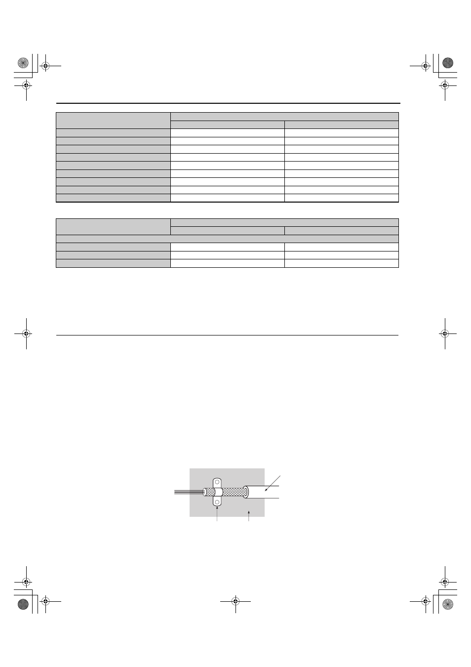
Use braided shield cable for the converter and motor wiring, or run the wiring through a metal conduit.
4.
Keep wiring as short as possible. Ground the shield on both the converter side and the motor side.
5.
Make sure the protective earthing conductor complies with technical standards and local safety regulations.
Figure D.2
Figure D.2 Ground Area
4A0030
300-052-244
43 A, 1.71 mH, 528 V
4A0040
300-052-245
58 A, 1.27 mH, 528 V
4A0060
300-052-246
86 A, 0.85 mH, 528 V
4A0100
300-052-247
145 A, 0.51 mH, 528 V
4A0130
300-052-248
210 A, 0.35 mH, 528 V
4A0185
300-052-249
300 A, 0.25 mH, 528 V
4A0270
300-052-250
410 A, 0.18 mH, 528 V
4A0370
300-052-251
560 A, 0.13 mH, 528 V
4A0630
300-052-251 (×2)
560 A, 0.13 mH, 528 V
Model
SAO ELECTRIC CORP.
Model
Ratings
400 V Class
4A0270
300-052-255
64 A, 0.0218 mH, 528 V
4A0370
300-052-256
87 A, 0.0158 mH, 528 V
4A0630
300-052-257
177 A, 0.0079 mH, 528 V
A – Braided shield cable
C – Cable clamp (conductive)
B – Metal panel
Model
SAO ELECTRIC CORP.
Model
Ratings
C
B
A
TOEP_C710656_07C_2_0.book 238 ページ 2015年1月9日 金曜日 午後6時23分