Figure 3.36, Figure 3.38, Figure 3.37 – Yaskawa D1000 Series Power Regenerative Converter User Manual
Page 80: 9 control circuit wiring
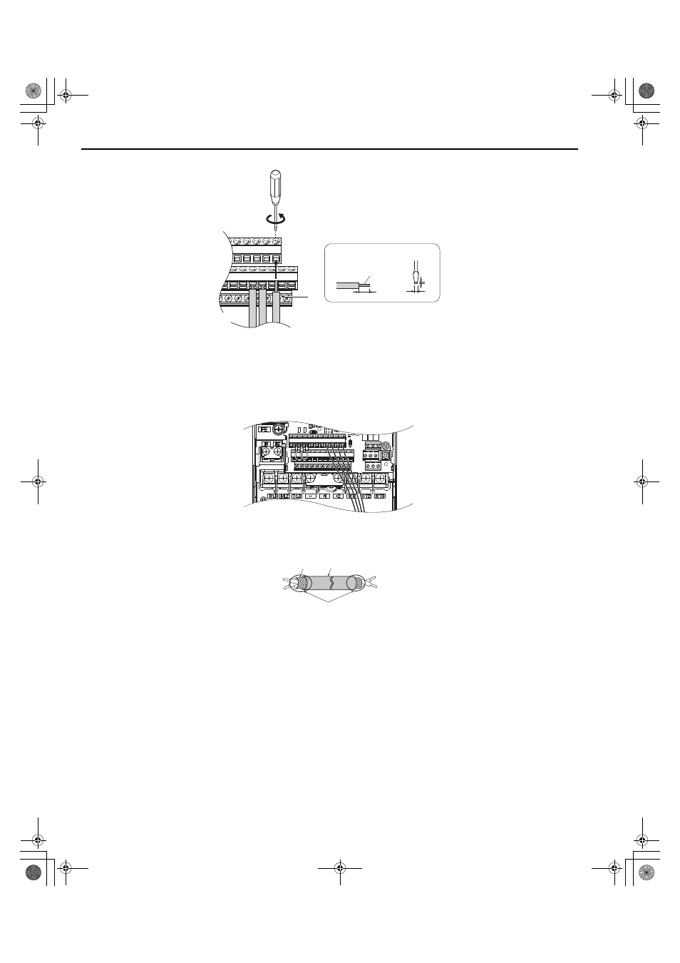
3.9 Control Circuit Wiring
80
YASKAWA ELECTRIC TOEP C710656 07C YASKAWA Power Regenerative Converter - D1000 Instruction Manual
Figure 3.39
Figure 3.36 Terminal Board Wiring Guide
Figure 3.40
Figure 3.37 Terminal Board Location Inside the Converter
For the control circuit wires, use shielded twisted-pair wires that have been prepared as shown in
.
Figure 3.41
Figure 3.38 Preparing the Ends of Shielded Cables
NOTICE: The analog signal wiring between the converter and the operator station or peripheral equipment should not exceed 50
meters when using an analog signal from a remote source. Failure to comply could result in poor system performance.
A – Loosen screw to insert wire.
C – Avoid fraying wire strands when
stripping insulation from wire.
Strip length 5.5 mm.
B – Single wire or stranded wire
D – Blade depth of 0.4 mm or less
E – Blade width of 2.5 mm or less
A – Converter side
D – Shield sheath (insulate with tape)
B – Insulation
E – Shield
C – Control device side
A
B
C
D
Preparing wire
terminal ends
YAI
YAI
A
E
B
C
D
TOEP_C710656_07C_2_0.book 80 ページ 2015年1月9日 金曜日 午後6時23分