O: operator-related settings – Yaskawa D1000 Series Power Regenerative Converter User Manual
Page 193
B.2 Parameter Tables
YASKAWA ELECTRIC TOEP C710656 07C YASKAWA Power Regenerative Converter - D1000 Instruction Manual
193
B
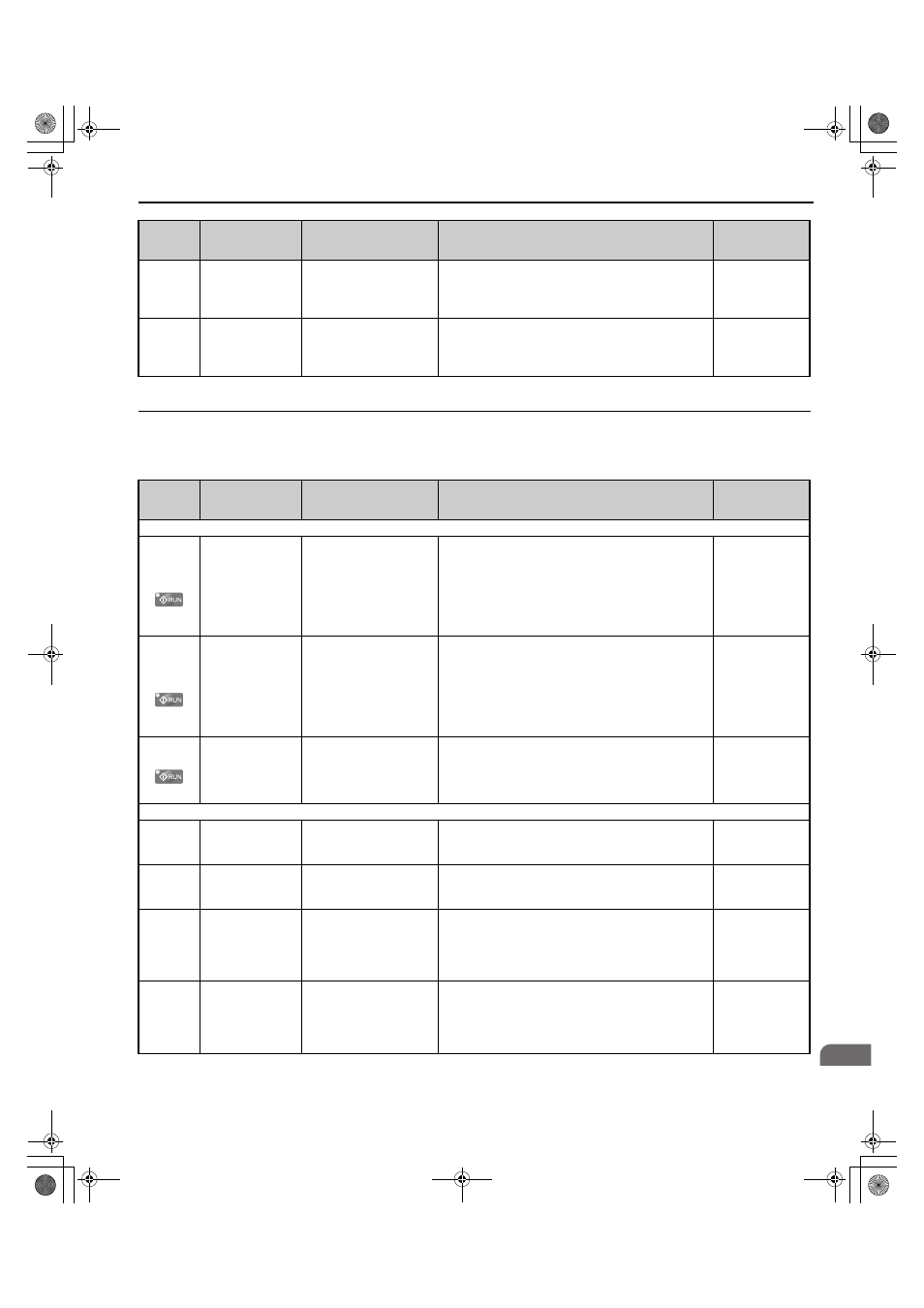
◆ o: Operator-Related Settings
The o parameters set up the digital operator displays.
L9-08
DC5 Conveter Unit
Replacement
Selection
Replacement DC5
Select when replacing DC5 with D1000, using the
peripheral devices as is.
0: Disable
1: Enable
Default: 0
Min.: 0
Max.: 1
L9-09
DC3 Conveter Unit
Replacement
Selection
Replacement DC3
Select when replacing DC3 with D1000, using the
peripheral devices as is.
0: Disable
1: Enable
Default: 0
Min.: 0
Max.: 1
<2> Default setting is dependent on parameter o2-04, Drive Model Selection.
No.
(Address
Hex)
Name
LCD Display
Description
Values
o1: Digital Operator Display Selection
o1-01
(500H)
Drive Mode
converter Monitor
Selection
User Monitor Sel
When the power supply is turned on, the operator will
display the following in order: DC Bus Voltage Reference,
DC Bus Voltage Feedback, DC Current Reference, Power
Supply Voltage, Power Supply Frequency, and U1-.
The o1-01 parameter sets the item to display instead of the
output voltage.
The o1-02 parameter sets the item to display at power up.
Default: 158
(Monitor U1-58)
Min.: 110
Max.: 914
o1-02
(501H)
User Monitor
Selection after
Power Up
Power-On Monitor
1: Frequency Ref
2: FWD/REV
3: Output Freq
4: Output Current
5: User Monitor
Selects the information displayed on the digital operator
when the power is turned on.
1: Output Voltage Reference
2: Output Voltage Feedback
3: Output Current
4: Input Voltage
5: User monitor item set in o1-01
Default: 1
Min.: 1
Max.: 5
o1-05
(504H)
LCD Contrast
Control
LCD Contrast
Sets the brightness of the LCD operator.
Default: 3
Min.: 0
Max.: 5
o2: Digital Operator Keypad Functions
o2-01
(505H)
LO/RE Key
Function Selection
LO/RE Key
0: Disabled
1: Enabled. LO/RE key switches between LOCAL and
REMOTE operation.
Default: 1
Min.: 0
Max.: 1
o2-02
(506H)
STOP Key Function
Selection
Oper STOP Key
0: Disabled
1: Enabled
0: Disabled. STOP key is disabled in REMOTE operation.
1: Enabled. STOP key is always enabled.
Default: 1
Min.: 0
Max.: 1
o2-03
(507H)
User Parameter
Default Value
User Default Sel
0: No Change
1: Save User Init
2: Clear User Init
0: No change.
1: Set defaults. Saves parameter settings as default values
for a User Initialization.
2: Clear all. Clears the default settings that have been
saved for a User Initialization.
Default: 0
Min.: 0
Max.: 2
o2-04
(508H)
Unit Model
Selection
Inverter Model #
Enter the converter model. Setting required only if
installing a new control board.
Default:
Determined by
converter model.
Min.: –
Max.: –
No.
(Address
Hex)
Name
LCD Display
Description
Values
TOEP_C710656_07C_2_0.book 193 ページ 2015年1月9日 金曜日 午後6時23分