4 alarm detection, Alarm codes, causes, and possible solutions, Alarm detection – Yaskawa D1000 Series Power Regenerative Converter User Manual
Page 120
120
YASKAWA ELECTRIC TOEP C710656 07C YASKAWA Power Regenerative Converter - D1000 Instruction Manual
5.4 Alarm Detection
5.4 Alarm Detection
◆ Alarm Codes, Causes, and Possible Solutions
Alarms are converter protection functions that do not necessarily cause the converter to stop. After removing the cause of
an alarm, the converter will return to the same status is was before the alarm occurred.
When an alarm has been triggered, the ALM light on the digital operator display blinks and the alarm code display
flashes. If a multi-function output is set for an alarm (H2- = 10), that output terminal will be triggered.
Note: If a multi-function output is set to close when an alarm occurs (H2- = 10), it will also close when maintenance periods are
reached, triggering alarms LT-1 through LT-4 (triggered only if H2- = 2F).
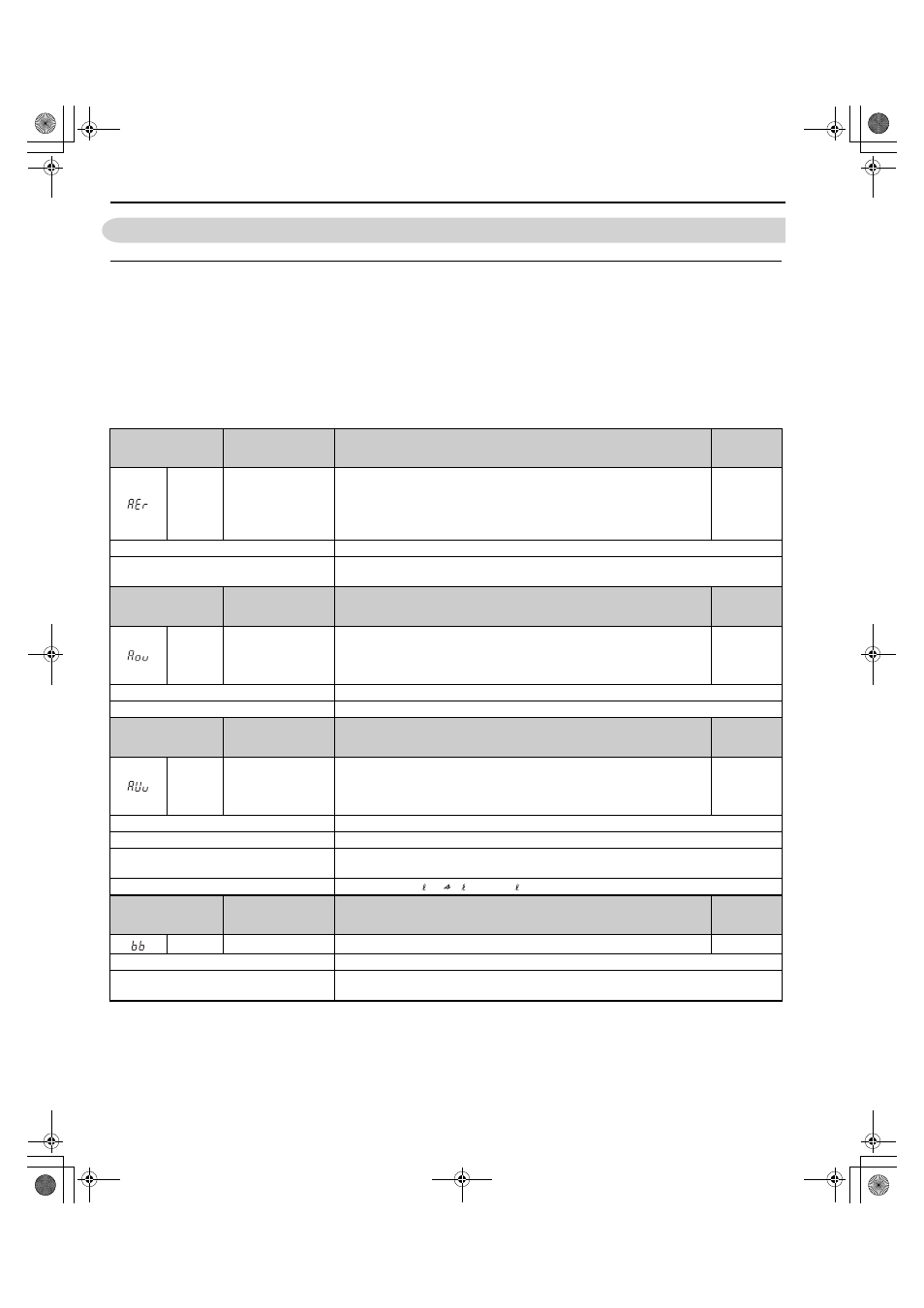
Table 5.7 Alarm Codes, Causes, and Possible Solutions
Digital Operator
Display
Minor Fault Name
Detail
Alarm
Output
(H2-=10)
AEr
Communication Option
Station Number Setting
Error (CC-Link,
CANopen,
MECHATROLINK)
Option card node address is outside of the acceptable setting range.
YES
Cause
Possible Solutions
Station number is set outside the possible
setting range.
Set the station number of the option card correctly.
Digital Operator
Display
Minor Fault Name
Detail
Alarm
Output
(H2-=10)
Aov
Power Supply
Overvoltage
The input power supply voltage became equal to or higher than the Input Power
Supply Overvoltage Detection Level.
200 V Class: Approximately 277 Vac
400 V Class: Approximately 554 Vac
YES
Cause
Possible Solutions
The input power supply voltage is too high.
Reduce the voltage to within the range in the power supply specifications.
Digital Operator
Display
Minor Fault Name
Detail
Alarm
Output
(H2-=10)
AUv
Power Supply
Undervoltage
The input power supply voltage became equal to or lower than the Input Power
Supply Undervoltage Detection Level.
200 V Class: Approximately 150 Vac
400 V Class: Approximately 300 Vac
YES
Cause
Possible Solutions
The power supply voltage is low.
Increase the power supply voltage.
A phase loss occurred in the input power
supply.
Check the input power supply for phase loss or an imbalance in the interphase voltages.
Investigate and correct the cause and reset the fault.
Voltage detection failed.
Correctly wire r1/ 11, 1/ 21, and t1/ 31.
Digital Operator
Display
Minor Fault Name
Detail
Alarm
Output
(H2-=10)
bb
Baseblock
converter output interrupted as indicated by an external baseblock signal.
N.A.
Cause
Possible Solutions
External baseblock signal was entered via one
of the multi-function input terminals (S1 to S8).
Check external sequence and baseblock signal input timing.
TOEP_C710656_07C_2_0.book 120 ページ 2015年1月9日 金曜日 午後6時23分