Yaskawa D1000 Series Power Regenerative Converter User Manual
Page 187
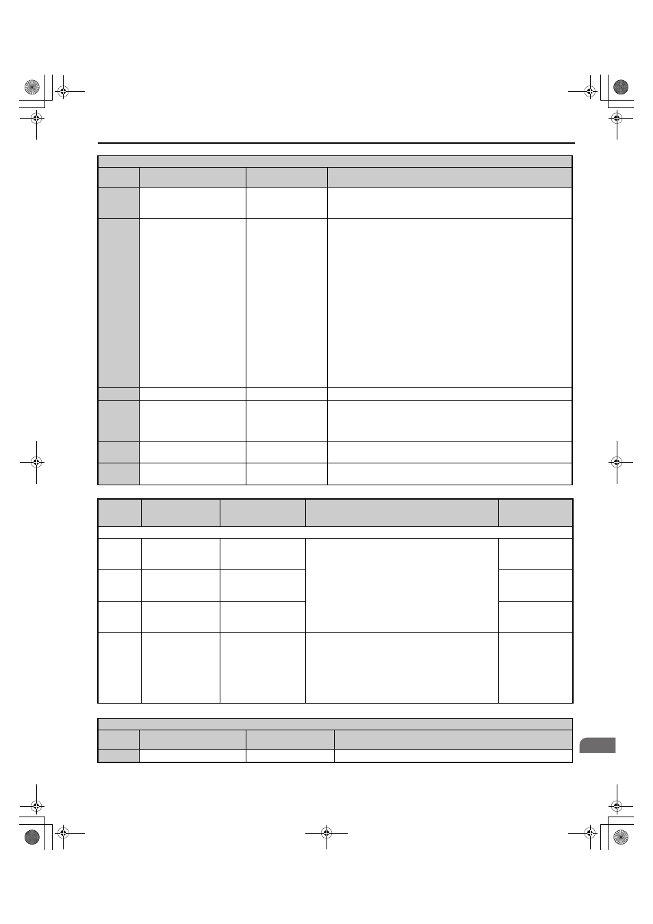
B.2 Parameter Tables
YASKAWA ELECTRIC TOEP C710656 07C YASKAWA Power Regenerative Converter - D1000 Instruction Manual
187
B
1B
Program lockout
Program Lockout
Open: Parameters cannot be edited (except for U1-01 if the reference
source is assigned to the digital operator).
Closed: Parameters can be edited and saved.
24 to 27
2C to 2F
External fault
External fault
24: NO/ Always Det,
Coast to Stop
25: NC/Always Det,
Coast to Stop
26: NO/During RUN,
Coast to Stop
27: NC/During RUN,
Coast to Stop
2C: NO/Always Det,
Alarm Only
2D: NC/Always Det,
Alarm Only
2E: NO/ During RUN,
Alarm Only
2F: NC/During RUN,
Alarm Only
24: N.O., Always detected, coast to stop
25: N.C., Always detected, coast to stop
26: N.O., During run, coast to stop
27: N.C., During run, coast to stop
2C: N.O., Always detected, alarm only (continue running)
2D: N.C., Always detected, alarm only (continue running)
2E: N.O., During run, alarm only (continue running)
2F: N.C., During run, alarm only (continue running)
47
Node Setup
Node SetUp
Closed: Node setup for SI-S3 enabled.
4B
Run Command
(2-wire Sequence)
Run Command3
Closed: Run
Note: To start operation, close the Stop Command (4C) and then open the
Run Command signal. After operation has started, it will continue even if
the Run Command signal is opened.
4C
Stop Command
(2-wire Sequence)
Stop Command3
Open: Stop.
Note: To stop operation, open the Stop Command signal.
67
Communications test mode
Comm Test Mode
Tests the MEMOBUS/Modbus RS-422/RS-485 interface. Displays
“PASS” if the test completes successfully.
No.
(Address
Hex)
Name
LCD Display
Description
Values
H2: Multi-Function Relay Outputs
H2-01
(40BH)
Terminal M1-M2
function selection
(relay)
M1-M2 Func Sel
Refer to
H2 Multi-Function Relay Output Settings on
for a description of setting values.
Note: Set unused terminals to F.
Default: 25H
Min.: 0
Max.: 160
H2-02
(40CH)
Terminal M3-M4
Function Selection
(Relay)
P1/PC Func Sel
Default: 26H
Min.: 0
Max.: 160
H2-03
(40DH)
Terminal M5-M6
Function Selection
(Relay)
P2/PC Func Sel
Default: 6H
Min.: 0
Max.: 160
H2-06
(437H)
kWh Monitor Pulse
Output Unit Selection
Pwr Mon Unit Sel
1: 1 kWh units
2: 10 kWh units
3: 100 kWh units
4: 1000 kWh units
Select the output unit of the multi-function contact when
H2-01 to H2-03 is set to 39 and 3A.
1: 1 kWh Units
2: 10 kWh Units
3: 100 kWh Units
4: 1000 kWh Units
Default: 1
Min.: 1
Max.: 4
H2 Multi-Function Relay Output Settings
H2-
Setting
Function
LCD Display
Description
0
During run
During RUN 1
Closed: A Run command is active or voltage is output.
H1 Multi-Function Digital Input Selections
H1-
Setting
Function
LCD Display
Description
TOEP_C710656_07C_2_0.book 187 ページ 2015年1月9日 金曜日 午後6時23分