Yaskawa D1000 Series Power Regenerative Converter User Manual
Page 191
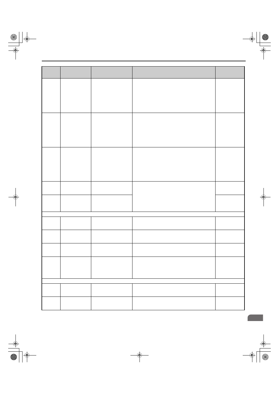
B.2 Parameter Tables
YASKAWA ELECTRIC TOEP C710656 07C YASKAWA Power Regenerative Converter - D1000 Instruction Manual
191
B
L2-05
(489H)
Undervoltage
Detection Level
(Uv)
PUV Det Level
There is normally no need to change this parameter from
the default value.
200 V Class
Default: 190 V
Min.: 150 V
Max.: 210 V
400 V Class
Default: 380 V
Min.: 300 V
Max.: 420 V
L2-21
(4D5H)
AUv Detection
Level
AC UV Level
Sets the undervoltage detection level for power supply
voltage (AC) in volts.
200 V Class
Default: 150 V
Min.: 100 V
Max.: 200 V
400 V Class
Default: 300 V
Min.: 200 V
Max.: 400 V
L2-35
(11E0H)
Momentary vrE
Detection Level
V Resonance Lvl
There is normally no need to change this parameter from
the default value. Protects the converter against
momentary increase of power supply voltage caused by
power supply resonance or other factors.
A vrE is detected when the detected power supply voltage
exceeds the value that is set in L2-35. Set the effective
value in L2-35.
Faults are not detected if you set this parameter to 0.
200 V Class
Default: 277 V
Min.: 0 V
Max.: 400 V
400 V Class
Default: 554 V
Min.: 0 V
Max.: 800 V
L2-36
Power Supply
Resonance
Detection Time
vrE Detect time
There is normally no need to change this parameter from
the default value.
The converter will stop temporarily, if a power supply
resonance is detected (rvE).
The converter will stop completely, if a power supply
resonance is detected (rvE) within the time set in L2-36 in
milliseconds for the number of time that is set in L2-37.
Default: 300 ms
Min.: 150 ms
Max.: 1000 ms
L2-37
Number of Power
Supply Resonance
Detection
vrE Detect Count
Default: 3
Min.: 1
Max.: 10
L5: Fault Restart
L5-01
(49EH)
Number of Auto
Restart Attempts
Num of Restarts
Sets the number of times the converter may attempt to
restart after the following faults occur: GF, oC, oH1, oL2,
ov, Uv1.
Default: 0 time
Min.: 0 time
Max.: 10 times
L5-02
(49FH)
Auto Restart Fault
Output Operation
Selection
Restart Sel
0: Flt Outp Disabld
1: Flt Outp Enabled
0: Fault output not active.
1: Fault output active during restart attempt.
Default: 0
Min.: 0
Max.: 1
L5-04
(4A0H)
Fault Reset Interval
Time
Flt Reset Wait T
Sets the amount of time to wait between performing fault
restarts.
Default: 10.0 s
Min.: 0.5 s
Max.: 600.0 s
L5-05
(46CH)
Fault Reset
Operation Selection
Fault Reset Sel
0: Continuous
1: Use L5-04 Time
0: Continuously attempt to restart while incrementing
restart counter only at a successful restart.
1: Attempt to restart with the interval time set in L5-04 and
increment the
restart counter with each attempt.
Default: 0
Min.: 0
Max.: 1
L7: Motoring Limit
L7-25
(628H)
Active Current Limit
at Power Supply
Side
Motoring I Limit
Sets the limit for the active current at the power supply
side.
Default: 200%
Min.: 0%
Max.: 200%
L7-26
(629H)
Active Current Limit
at Regeneration Side
Regen I Limit
Sets the limit for the active current at the regeneration side.
Default: 200%
Min.: 0%
Max.: 200%
No.
(Address
Hex)
Name
LCD Display
Description
Values
TOEP_C710656_07C_2_0.book 191 ページ 2015年1月9日 金曜日 午後6時23分